
Views: 425 Author: Nanjing Taidun Publish Time: 2026-05-08 Origin: Site
Content Menu
● What Is a Steel Frontal Panel and Why Does It Matter?
>> Primary Functions of a Frontal Panel
>> The Consequences of Poor Panel Design
● The PIANC-Recommended Minimum Thickness Requirements
>> Minimum Steel Thickness by Exposure Condition
>> Corrosion Allowance Requirements
● The PIANC-Compliant Hull Pressure Formula
>> The Formula
>> Understanding the Valid Panel Area
>> Allowable Hull Pressure Values (Py)
● Step-by-Step Calculation Method for Frontal Panel Sizing
>> Step 1 – Determine Total Reaction Force (ΣR)
>> Step 2 – Determine Allowable Hull Pressure (Py)
>> Step 3 – Calculate Required Valid Panel Area
>> Step 4 – Determine Panel Dimensions
>> Step 5 – Verify Hull Pressure
>> Step 6 – Determine Required Steel Thickness
● The 60-40 Load Distribution Principle
● Structural Strength Calculation for Frontal Panels
>> Uniformly Distributed Load Calculation
>> Non-Uniformly Distributed Load Calculation
● Key Design Requirements Per PIANC WG211
>> Key Requirements for Frontal Panel Design
● Closed vs. Open Frontal Panel Designs
● Steel Grade Selection for Frontal Panels
● User Feedback – Real-World Perspectives on Frontal Panel Design
● Frontal Panel Design Checklist
● How Nanjing Taidun Supports Your Frontal Panel Needs
Steel frontal panels are the unsung heroes of any marine fender system. They stand between your rubber fenders and the vessel hull, distributing massive impact forces across a wide area to prevent both rubber failure and hull damage.
But here is a truth I have learned over two decades of manufacturing OEM rubber fender systems: frontal panel failure is one of the most common—and most preventable—causes of premature fender system breakdown.
I have seen panels buckle under load because the design engineer guessed at thickness requirements. I have watched welds fail because corrosion allowances were ignored. And I have witnessed perfectly good rubber fenders destroyed because the steel panel above them was under-engineered.
This guide provides a complete, step-by-step method for how to calculate required steel frontal panel thickness using PIANC-compliant formulas . Whether you are designing a new berth, upgrading an existing facility, or sourcing OEM components, these engineering principles will ensure your panels perform—and last.
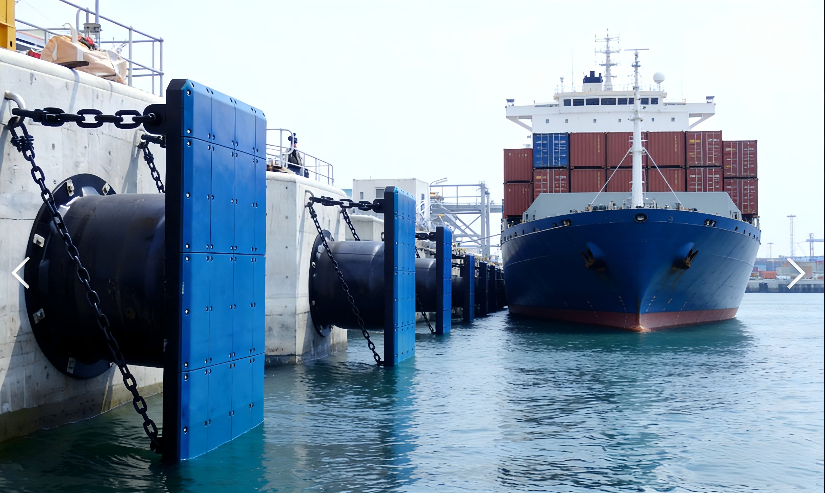
A steel frontal panel (also called a fender panel or front frame) is the rigid steel structure mounted between the rubber fender unit and the vessel hull .
Before diving into proper design, let us understand what happens when frontal panels fail :
| Design Flaw | Consequence |
|---|---|
| Uneven force distribution | Localized rubber cracking, tearing, and permanent deformation |
| Insufficient structural strength | Panel bending, weld failure, or complete detachment |
| Incompatible mounting dimensions | Misalignment, bolt shear, and installation delays |
| Substandard material selection | Rapid corrosion, thickness reduction within 2–3 years |
| Non-compliance with PIANC | Rejection by classification societies, insurance issues |
A properly designed frontal panel is not expensive—it is essential. And it starts with the correct thickness calculation.
Before performing detailed calculations, it is essential to understand the baseline requirements established by PIANC (The World Association for Waterborne Transport Infrastructure) .
According to PIANC guidelines, the minimum thickness for steel in fender panels depends on environmental exposure :
| Exposure Condition | Minimum Thickness | Application Example |
|---|---|---|
| Plates exposed on two surfaces | 12 mm | Seawater on both sides (fully exposed) |
| Plates exposed on one surface | 9–10 mm | One side exposed to seawater |
| Internal members (not exposed) | 8 mm | Inside sealed box panels |
> *"International Navigation Association recommends 12mm as the absolute minimum when exposed to seawater on both faces, 10mm for exposure to one face and 8mm for internal sections not exposed to corrosion."*
These are absolute minimums. For larger vessels, high-energy berths, or aggressive corrosion environments, greater thickness is required.
No paint lasts forever. In marine environments, typical coating life is 10–15 years . After coating failure, steel corrodes.
Recommended corrosion allowances :
| Environment | Recommended Corrosion Allowance |
|---|---|
| Cold water climates | 3 mm per exposed face |
| Warm/tropical waters | Higher allowance required |
> *"If corrosion allowances are not specified, they will invariably be ignored and the life expectancy of the panel will be drastically reduced."*
Pro Tip: Always add corrosion allowance to your calculated structural thickness. A panel calculated to require 12 mm structural steel should start at 15–18 mm to account for 10–15 years of corrosion.
The governing formula for frontal panel design is the hull pressure equation :
> P = ΣR ÷ (A₁ × B₁) ≤ Py
| Variable | Description | Unit |
|---|---|---|
| P | Actual hull pressure | kN/m² (kPa) or psi |
| ΣR | Sum of maximum reaction forces of all rubber fenders in one system | kN |
| A₁ | Valid panel width (excluding lead-in chamfers) | m |
| B₁ | Valid panel height (excluding lead-in chamfers) | m |
| Py | Allowable hull pressure (vessel-specific) | kN/m² (kPa) |
A critical distinction: Valid panel area excludes lead-in chamfers .
Example calculation:
| Parameter | Value |
|---|---|
| Total panel width | 2,500 mm |
| Lead-in chamfers (each side) | 150 mm |
| Valid width (A₁) | 2,500 - 300 = 2,200 mm (2.2 m) |
| Total panel height | 1,800 mm |
| Lead-in chamfers (top/bottom) | 100 mm |
| Valid height (B₁) | 1,800 - 200 = 1,600 mm (1.6 m) |
> *"If chamfers are incorrectly included in the valid area, the calculated pressure will be artificially low—leading to underestimation of hull pressure and potential damage."*
When vessel-specific data is unavailable, PIANC provides the following recommended allowable hull pressures :
| Vessel Type | Allowed Hull Pressure (kN/m²) |
|---|---|
| General oil tanker | 250–350 |
| Coastal tanker | 250–350 |
| Bulk carrier / Bulk ship | 150–250 |
| Panamax container ship | 150–250 |
| Sub-Panamax container ship | 300–400 |
| Post-Panamax container ship | 400–500 |
| General cargo ship | 300–600 |
| Gas carrier (LNG/LPG) | 100–200 |
Design note: Gas carriers have the lowest allowable hull pressure (100–200 kN/m²) due to their thin, specialized hull structures. These applications require larger panel areas or lower reaction force fenders.
Here is a worked example demonstrating how to calculate required steel frontal panel thickness using the PIANC-compliant method.
First, calculate the combined reaction force of all fenders in the system.
| Parameter | Value |
|---|---|
| Number of fenders in system | 2 |
| Reaction force per fender (at design deflection) | 450 kN each |
| ΣR (Total reaction force) | 900 kN |
Select based on vessel type using the table above.
| Parameter | Value |
|---|---|
| Vessel type | Panamax container ship |
| Py (Allowable hull pressure) | 200 kN/m² |
Rearrange the formula to solve for required panel area:
> Required Area = ΣR ÷ Py
| Calculation | Result |
|---|---|
| Required Area = 900 kN ÷ 200 kN/m² | 4.5 m² |
Select dimensions that achieve the required area while fitting within the berth geometry.
| Option | Width (A₁) | Height (B₁) | Area (A₁×B₁) |
|---|---|---|---|
| Option 1 | 2.5 m | 1.8 m | 4.5 m² |
| Option 2 | 3.0 m | 1.5 m | 4.5 m² |
| Option 3 | 2.2 m | 2.05 m | 4.5 m² |
Confirm that actual pressure does not exceed allowable:
> Actual P = ΣR ÷ (A₁×B₁)
| Calculation | Result |
|---|---|
| Actual P = 900 kN ÷ 4.5 m² | 200 kN/m² |
| Allowable Py | 200 kN/m² |
| Verdict | ACCEPTABLE (P = Py) |
Now that panel dimensions are established, calculate the required structural thickness.
Load-bearing requirements for frontal panels :
| Requirement | Design Consideration |
|---|---|
| Resistance to bending moments | Panel must not deflect under load |
| Resistance to shear forces | Weld integrity and stiffener spacing |
| Resistance to local impact | Point load capacity from vessel belting |
| No deformation during compression | Flatness after repeated loading |
Empirical thickness guidelines :
| Vessel Size | Recommended Panel Thickness |
|---|---|
| Small vessels (<5,000 DWT) | 12–16 mm |
| Medium vessels (5,000–50,000 DWT) | 16–22 mm |
| Large vessels (>50,000 DWT) | 22–30 mm |
| Ultra-large (VLCC, ULCC) | 30–40 mm |
Minimums (per PIANC): Plates exposed on two faces = 12 mm minimum .
In well-designed frontal panels, load distribution across the rubber fender surface should follow a graduated pattern :
| Zone | Target Load Percentage | Design Strategy |
|---|---|---|
| Panel center (primary contact zone) | 60% | Maximum stiffness, minimal deflection |
| Panel edges (transition zone) | 40% | Graduated stiffness to prevent stress concentration |
This graduated approach prevents localized rubber cracking by ensuring no single point absorbs disproportionate energy.
Implementation method: Use graduated stiffener spacing or variable plate thickness—stiffer at center, more flexible at edges.
For detailed engineering analysis, consider both uniform and non-uniform load distributions .
> R = F + (q × L)
Where :
- R = Reaction force (kN)
- F = Balance force (kN)
- q = Uniformly distributed load (kN/m)
- L = Effective contact length (m)
Maximum torque is then calculated as:
> Mmax = (R × L₁ × L₂⊃2;) ÷ L⊃2; = (R × L₁⊃3;) ÷ L⊃2; + (F × L₁)
> R = F + Q
Where :
- Q = Contact load (kN)
- F = Balance force (kN)
Maximum torque for non-uniform distribution:
> Mmax = Q × (L₂ + 0.5L₃) = F × L₁
Note: These calculations should be performed by a qualified structural engineer using appropriate finite element analysis (FEA) software. The formulas provided here are for initial sizing and verification.
PIANC published updated guidelines in 2024 (WG211), replacing the previous WG33 (2002) . Here is what has changed.
The PIANC Guidelines for the Design of Fender Systems were updated in 2024. WG211 introduces several important changes :
| Aspect | WG33 (2002) | WG211 (2024) |
|---|---|---|
| Safety approach | Global safety factor | Partial resistance factors |
| Correction factors | Limited | Expanded (includes multiple fender contact) |
| Fender selection guidance | Basic | Comprehensive (Chapter 6) |
| Hull pressure guidance | Basic | Updated with panel sizing effects |
PIANC frontal panel design must consider :
| Requirement | Description |
|---|---|
| Hull pressure compliance | P = ΣR/(A₁×B₁) ≤ Py |
| Bending moment resistance | Panel must not yield under design load |
| Shear force resistance | Weld and stiffener integrity |
| Local impact resistance | Point loads from vessel belting |
| Corrosion protection | Paint system + corrosion allowance |
| UHMW-PE attachment | Secure face pad mounting |
| Chain connection points | Reinforced lifting/pulling points |
| Lead-in chamfers | 15–30° angles to reduce snagging |
Frontal panels are manufactured in two primary configurations .
Construction: Facing panel + longitudinal girders + cross girders
Advantages:
- Lighter weight
- Easier inspection and maintenance
- Lower manufacturing cost
Disadvantages:
- More exposed surfaces for corrosion
- Potential debris accumulation
Construction: Facing panel + back panel + internal stiffeners (fully sealed)
Advantages:
- Superior corrosion protection (internal surfaces sealed)
- Higher stiffness-to-weight ratio
- Cleaner appearance
Disadvantages:
- Heavier
- Harder to inspect internal welds
- Water ingress risk if seals fail
> *"Rubber fender fixing points should be locally reinforced and sealed to prevent water ingress if closed box panels are used."*
| Application | Recommended Type |
|---|---|
| High-corrosion environments | Closed box (with proper sealing) |
| Easy-access berths | Open type (easier inspection) |
| Large vessel terminals | Closed box (higher stiffness) |
| Budget-conscious projects | Open type |
Nanjing Taidun manufactures both configurations to meet specific project requirements.
A36 steel offers :
- Good weldability
- Predictable performance under cyclic loading
- Wide availability
- Cost-effectiveness for most applications
For very large vessels or critical infrastructure, higher-grade steel may be specified.
We asked our global OEM clients about their experience with frontal panel design and failures. Here is what they shared:
> *"We learned the hard way that minimum PIANC thickness is exactly that—minimum. Our first panels were 12mm for a medium container berth. After three years, corrosion had reduced effective thickness to 9mm in spots. We saw visible deflection under load. Our second set was 16mm with 3mm corrosion allowance. Seven years later, they are still perfect."*
> — *Maintenance Manager, Southeast Asian Terminal*
> *"The chamfer area exclusion in hull pressure calculation caught us off guard. Our first panel design used total panel dimensions in the formula, not the valid area. The result? Actual hull pressure was 15% higher than calculated. No damage occurred, but we were operating outside PIANC limits for months before we caught the error."*
> — *Port Engineer, European Container Terminal*
> *"We upgraded from open-type to closed-box panels at our LNG terminal. The initial cost was higher, but the corrosion protection has been worth every penny. After five years in a tropical marine environment, they look almost new. Our old open panels would have needed recoating by now."*
> — *Facility Director, Middle East LNG Terminal*
Use this checklist when specifying frontal panels for your fender system:
| Check | Item |
|---|---|
| ☐ | ΣR calculated from all fenders in system |
| ☐ | Py selected from PIANC table or vessel-specific data |
| ☐ | Valid panel area (A₁×B₁) excludes chamfers |
| ☐ | P = ΣR/(A₁×B₁) ≤ Py verified |
| ☐ | Minimum thickness per PIANC (12/10/8 mm) satisfied |
| ☐ | Corrosion allowance added (3 mm+ per exposed face) |
| ☐ | Open vs. closed type selected appropriately |
| ☐ | Lead-in chamfers designed (15–30°) |
| ☐ | UHMW-PE attachment method specified |
| ☐ | Weld sizes and types defined |
| ☐ | Paint system specified (C5-M marine grade) |
| ☐ | Lifting points designed |
At Nanjing Taidun Marine Equipment Engineering Co., Ltd. , we understand that how to calculate required steel frontal panel thickness is just the beginning. We provide complete OEM frontal panel solutions.
Our capabilities include:
| Service | Description |
|---|---|
| Custom panel design | Tailored to your fender configuration and vessel mix |
| PIANC-compliant engineering | Full adherence to WG211 guidelines |
| Multiple steel grades | Q235B (A36), Q345B, and marine-grade options |
| Open or closed box | Both configurations available |
| Corrosion protection | C5-M epoxy paint systems, galvanizing options |
| UHMW-PE face pads | Integrated attachment |
| Third-party certification | ABS, BV, DNV, LR, CCS available |
| Full documentation | Engineering calculations, material certs, test reports |
We serve brand owners, wholesalers, and production facilities in over 80 countries. When you partner with Nanjing Taidun, you get factory-direct pricing, custom engineering, and full PIANC compliance documentation .
How to calculate required steel frontal panel thickness comes down to four steps:
1. Calculate total reaction force (ΣR)
2. Determine allowable hull pressure (Py)
3. Solve for required valid panel area (A₁×B₁ = ΣR/Py)
4. Add corrosion allowance and verify against PIANC minimums
Do not leave your fender system's structural integrity to guesswork. Use the PIANC-compliant formula. Add corrosion allowance. And partner with an experienced OEM who understands both the math and the real-world conditions.
[Contact the Nanjing Taidun Engineering Team] for a free frontal panel consultation. Send us your fender specifications and vessel mix, and we will provide recommended panel dimensions, thickness, and steel grade—complete with PIANC compliance verification.
1. Nanjing Taidun Marine Equipment Engineering Co., Ltd. *Closed Open Fender Panel*. [https://www.taidunmarine.com/closed-open-fender-panel.html]
2. Nanjing Taidun Marine Equipment Engineering Co., Ltd. (2026). *A36 Steel Frontal Panel for Rubber Fender: Load Distribution Design*. [https://www.taidunmarine.com/a36-steel-frontal-panel-for-rubber-fender-load-distribution-design.html]


