

Views: 251 Author: Site Editor Publish Time: 2026-09-16 Origin: Site
Content Menu
● Why Bollards and Fender Panels Are Often Confused
● What Marine Mooring Bollards Actually Do
>> Bollard Capacity Is Not Fender Capacity
>> Selecting the Right Bollard Type
● Kinetic Energy Transfer: A Practical Berthing Sequence
● Expert Design Checklist for OEM Buyers
● New Industry Insight: Site Data Is Now a Competitive Advantage
● Common Specification Errors to Avoid
>> Specifying fenders only by energy absorption
>> Buying bollards only by nominal tonnage
>> Ignoring the connection details
>> Using one product design for every berth
>> Separating fender and bollard procurement
● Why Choose Taidun for OEM Marine Berthing Equipment
● FAQ
>> What is the main difference between marine mooring bollards and fender panels?
>> Can a mooring bollard absorb vessel berthing impact?
>> How is marine fender capacity selected?
>> What bollard SWL should I choose?
>> Why are UHMW-PE pads used on fender panels?
>> Can Taidun provide both fender panels and mooring bollards as OEM products?
>> What information should I send for an OEM quotation?
● Request an OEM Berthing Solution
At Nanjing Taidun Marine Equipment Engineering Co., Ltd, we help international brands, wholesalers, shipyards, and marine-equipment manufacturers build safer berthing and mooring systems through OEM production of marine rubber fenders, mooring bollards, and anchoring equipment. The central point in the discussion of marine mooring bollards vs fender panels is simple but often misunderstood: fender panels manage a vessel's berthing kinetic energy, while mooring bollards manage the forces acting on a vessel after it is alongside.
These components are installed along the same quay, but they do not perform the same task and should never be specified as if they do. A fender panel system protects the vessel and berth during contact; a mooring bollard secures the vessel after berthing against wind, current, tide, surge, wake, and line loads. Designing them as one coordinated system is essential to terminal safety, asset durability, operational uptime, and lifecycle cost.
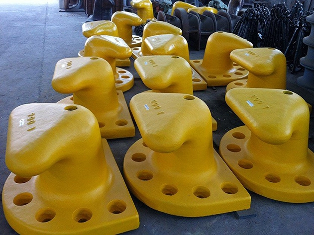
In many early-stage marine projects, buyers ask whether higher-capacity bollards can compensate for smaller fender panels, or whether strong fender panels can reduce the need for robust mooring hardware. From an engineering standpoint, the answer is no.
A vessel arriving at a berth has motion. Its mass and approach velocity create kinetic energy. That energy must be controlled at the point of first contact. A vessel safely alongside still experiences environmental and operational forces. Those forces must be restrained through its mooring lines and transferred into the bollards and berth structure.
The systems interact, but their core duties differ:
| System | Primary function | Main load condition | Typical equipment |
|---|---|---|---|
| Marine fender panel system | Absorbs berthing energy and limits reaction force | Vessel approach and contact | Rubber fender body, UHMW-PE face pad, steel frontal panel, chains, anchors |
| Marine mooring bollard system | Secures the vessel alongside the berth | Mooring-line tension caused by environmental loads | T-head bollard, horn bollard, double bitt, quick-release hook, base plate and anchors |
| Combined berth system | Protects the berth throughout the vessel call | Berthing, mooring, tidal movement and departure | Fender panels, bollards, chains, anchors, quay structure |
A marine berth therefore needs both systems. The fender panel is the impact-management system. The bollard is the restraint system.
PIANC's latest fender guidance emphasizes that fender systems are designed to absorb a berthing vessel's energy and transfer the associated reaction safely into the supporting structure. It also places greater emphasis on site-specific vessel and operating data rather than relying only on generic assumptions.
The rubber fender body is the primary energy-absorbing component. When compressed by the vessel, it deforms in a controlled way. This deformation converts vessel motion into strain energy inside the rubber system while creating a reaction force that slows and stops the vessel's lateral movement.
Depending on the project requirements, Taidun OEM fender solutions may include:
- Cone fenders for high-energy berths and large frontal panels
- Cell fenders for robust energy absorption and wide panel support
- Super arch fenders for general port, jetty, and wharf applications
- Sliding or fixed fender panels with low-friction UHMW-PE face pads
- Custom steel frontal frames engineered around vessel geometry and berth layout
- Chains, shackles, anchor bolts, and mounting accessories supplied as an integrated package
The goal is not simply to select a rubber fender with a high rated energy value. The fender must also control the corresponding reaction force, vessel hull pressure, panel deflection, chain load, anchor load, and concrete-structure load.
A rubber fender without a properly designed frontal panel may create concentrated hull pressure, poor contact geometry, excessive local wear, or insufficient protection across changing tidal levels. The panel spreads the load over a larger contact area and provides a durable low-friction surface for the vessel hull.
A well-designed panel system can help:
- Reduce contact pressure on the vessel hull
- Distribute berthing loads more evenly
- Accommodate vessel movement caused by tide and draft variation
- Protect the rubber fender body from abrasion
- Improve compatibility with different vessel sizes
- Reduce maintenance frequency over the berth's service life
After the vessel has completed its berthing maneuver, mooring lines are connected to shore-side bollards. At that stage, the principal challenge changes from stopping motion to controlling position.
A marine mooring bollard transfers line tension from the vessel into the berth structure. The mooring arrangement must resist external loads caused by:
- Wind pressure on the vessel's exposed area
- Current acting on the underwater hull
- Tidal movement and changing water levels
- Waves, swell, and passing-vessel wake
- Surge caused by loading, unloading, or vessel motion
- Interaction forces from nearby ships
- Emergency or abnormal operating conditions
OCIMF's Mooring Equipment Guidelines describe a system-based approach in which mooring lines, shipboard fittings, machinery, and supporting structures are designed together. The guidelines identify environmental forces—including wind, current, tides, and vessel interaction—as central loads that the mooring system must resist.
A common procurement mistake is to treat a bollard's Safe Working Load as an indicator of berthing-impact capacity. It is not.
A 100-ton, 150-ton, or 200-ton bollard rating describes the bollard's intended mooring-line load capacity under specified design conditions. It does not mean the bollard should receive direct vessel impact, nor does it replace a fender system's energy-absorption role.
Similarly, an oversized fender system cannot solve poorly designed mooring geometry. If the vessel is exposed to strong current, large tidal variation, high wind, or frequent wake, the mooring layout and bollard capacity must be designed for those sustained and cyclic loads.
At Taidun, we typically recommend choosing a bollard type only after reviewing the vessel range, berth layout, line angles, target SWL, environmental load cases, foundation arrangement, and local terminal operating practices.
| Bollard type | Suitable application | Key advantage |
|---|---|---|
| T-head bollard | General ports, bulk terminals, container berths | Supports mooring lines from multiple directions |
| Horn bollard | General-purpose mooring locations | Simple line handling and dependable geometry |
| Double bitt bollard | Heavy-duty berths and demanding mooring patterns | Strong line control and multi-line capability |
| Single bitt | Smaller berths and limited-space applications | Compact, practical configuration |
| Quick-release hook | Oil, gas, LNG, chemical, and high-efficiency terminals | Enables faster release and can support remote monitoring |
The correct bollard is not always the highest-rated one. The right choice is the one that matches the designed mooring load, line lead angle, operational method, foundation strength, corrosion environment, and terminal safety procedures.
Understanding the timeline of a vessel call makes the difference between a bollard and fender panel clear.
The vessel approaches the berth with residual lateral velocity. Pilots, tugboats, thrusters, current, wind, and berth geometry influence this phase.
Primary equipment at work: Fender panel system.
The vessel hull contacts the low-friction face pad of the fender panel. The frontal panel distributes contact load, while the rubber fender compresses and absorbs kinetic energy.
Primary equipment at work: Panel, UHMW-PE pad, rubber fender, chains, anchor bolts, supporting structure.
The fender system slows the vessel and limits reaction force. The berth structure receives the resulting load through the fender connection system.
Primary equipment at work: Fender system and quay structure.
Once alongside, crews pass and tension mooring lines to bollards or quick-release hooks. The vessel is positioned and restrained.
Primary equipment at work: Bollards, mooring lines, shipboard fittings, berth foundation.
During cargo transfer, loading, unloading, passenger handling, repair, or standby, environmental forces continue to act on the vessel. Fenders accommodate limited vessel movement and prevent hard contact. Bollards hold the vessel in its intended position.
Primary equipment at work: Both systems, performing different but coordinated functions.
For international brands, wholesalers, and engineering firms sourcing OEM marine equipment, product selection should start with technical inputs—not only a product catalog or a target price.
Before requesting a bollard and fender proposal, prepare the following information.
1. Design vessel range: Vessel type, LOA, beam, draft, displacement, and berth frequency.
2. Berthing conditions: Approach velocity, angle, tug assistance, current, wind, wave climate, and pilot practices.
3. Berth geometry: Quay wall type, water depth, tidal range, fender elevation, and spacing.
4. Hull-contact requirements: Required panel height, panel width, face-pad arrangement, and allowable hull pressure.
5. Structural constraints: Concrete strength, embedded anchors, steelwork configuration, and allowable reaction loads.
6. Environmental conditions: Temperature, UV exposure, seawater corrosion, ice, abrasion, and chemical exposure.
1. Required SWL: Based on a complete mooring analysis, not an arbitrary nominal capacity.
2. Vessel mooring arrangement: Number of lines, line directions, spring lines, breast lines, and lead angles.
3. Bollard location and spacing: Coordinated with vessel fairleads, shipboard mooring arrangement, and berth length.
4. Foundation design: Reinforcement, anchor-bolt configuration, concrete dimensions, and load path.
5. Operating environment: Wind, current, tide, wave, traffic wake, and possible dynamic loading.
6. Material and coating requirements: Cast steel, ductile iron, welded steel, galvanizing, epoxy system, or project-specific marine coating.
Our OEM recommendation: Treat these inputs as a design brief. A reliable supplier should review them before finalizing drawings, material selection, mold configuration, manufacturing tolerances, and inspection requirements.
The biggest shift in modern fender engineering is the move away from "catalog-only" selection toward site-specific design verification.
PIANC WG211, the current guideline for fender-system design, supersedes the earlier WG33 approach and calls for an integrated design process. It distinguishes characteristic berthing energy from design berthing energy, accounts for uncertainty through partial energy factors, and strongly favors project-specific operational information where available.
For berth owners and OEM buyers, this has several implications:
- Historic vessel calls can reveal the real design-vessel mix.
- Pilot and tug-master feedback can improve berthing-velocity assumptions.
- Site observations can identify abnormal wave, wake, current, or tidal behavior.
- Existing fender inspection records can expose poor contact zones or repeated overload patterns.
- A terminal may need different fender performance at different locations along the same berth.
In other words, the most reliable design is not necessarily the largest fender or highest-capacity bollard. It is the system that is matched to real operational conditions and verified from vessel contact through to the berth foundation.
Energy absorption is important, but it is incomplete without reaction force, deflection, panel configuration, hull pressure, chain loads, anchor loads, and structural capacity.
A 150-ton bollard may be unsuitable if the line lead angle is wrong, the foundation is under-designed, or the expected environmental load case exceeds the mooring plan.
A high-quality rubber fender or cast bollard can still fail in service if anchors, welds, chains, base plates, reinforcement, corrosion protection, or installation tolerances are neglected.
Container terminals, bulk jetties, Ro-Ro facilities, floating docks, offshore berths, and naval facilities have different vessel behaviors and operating risks. Product standardization is valuable, but it must not override project-specific engineering.
When fender panels, rubber fenders, bollards, anchors, and structural drawings are sourced independently, interface risks increase. Coordinated technical review reduces clashes in spacing, elevation, load paths, installation sequencing, and maintenance access.
Nanjing Taidun Marine Equipment Engineering Co., Ltd supports overseas brands and professional buyers that need a dependable OEM manufacturing partner rather than a one-size-fits-all catalog supplier.
Our approach centers on technical coordination, consistent manufacturing, and long-term partnership. We can support projects involving marine rubber fenders, fender panels, mooring bollards, anchoring systems, and related berth-protection accessories.
For OEM and wholesale partners, this means:
- Customized product dimensions, load ratings, materials, and branding options
- Technical drawing support based on project requirements
- Integrated supply of fender bodies, steel panels, face pads, chains, anchors, and bollards
- Quality-control processes aligned with agreed specifications
- Export-oriented packaging and shipment coordination
- Support for private-label marine-equipment programs
- Practical communication from quotation to production and delivery
The best marine berth solution is not a choice between a bollard and a fender panel. It is a coordinated system in which each component handles the load it was designed to manage.
Marine fender panels and rubber fenders absorb a vessel's berthing kinetic energy and reduce impact force during contact with the berth. Marine mooring bollards secure the vessel after it is alongside by transferring mooring-line tension into the berth structure.
No. A bollard is designed for mooring-line loads, not direct vessel impact. Direct impact can damage the bollard, anchor system, concrete foundation, vessel, or all of these components. A properly designed fender system should handle berthing impact.
Fender capacity is selected from the vessel's design displacement, approach velocity, berth geometry, contact arrangement, environmental conditions, eccentricity, and other correction factors. Designers must also verify reaction force, deflection, hull pressure, panel design, and berth-structure capacity.
The required Safe Working Load should come from a mooring analysis that considers vessel size, line arrangement, lead angles, wind, current, tide, wave conditions, and operating procedures. Selecting a bollard based only on a standard nominal rating can create safety risks.
UHMW-PE pads provide a durable, low-friction contact surface between the vessel hull and the steel fender panel. They help reduce hull abrasion and allow controlled vertical vessel movement caused by tide, draft changes, loading, and vessel motion.
Yes. Nanjing Taidun Marine Equipment Engineering Co., Ltd can provide OEM support for marine rubber fenders, fender panel systems, mooring bollards, anchors, chains, fittings, and related berth-protection equipment. Providing coordinated equipment can reduce interface risks between components.
Send your vessel data, berth drawings, required capacities, operating conditions, preferred materials, coating requirements, technical standards, quantities, target delivery schedule, branding needs, and any available engineering specifications. The more complete the design input, the more accurate the technical and commercial proposal can be.
If you are a marine-equipment brand, wholesaler, contractor, port operator, shipyard, or terminal developer, send Nanjing Taidun Marine Equipment Engineering Co., Ltd your berth drawings, vessel information, required fender energy, bollard SWL, and target market requirements.
Our engineering and manufacturing team can help you develop a coordinated OEM solution for marine rubber fenders, fender panels, mooring bollards, and anchoring equipment—designed to manage vessel impact, mooring loads, installation realities, and long-term marine service conditions.
1. PIANC. *PIANC Fender Guidelines 2024*. The guideline supersedes PIANC MarCom WG33 and provides guidance on fender-system design, manufacturing, testing, safety, durability, and total cost of ownership. [PIANC Fender Guidelines 2024] [pianc]
2. Trelleborg Marine & Infrastructure. *PIANC WG211 Fender Design Guidelines*. Overview of the WG211 update, including characteristic and design berthing energy, fender selection, performance verification, and site-specific design information. [PIANC WG211 Fender Design Guidelines] [trelleborg]
3. OCIMF. *Mooring Equipment Guidelines (MEG4)*. Recommended minimum requirements for ship designers, terminal designers, ship operators, and mooring-line manufacturers. [Mooring Equipment Guidelines (MEG4)] [ocimf]
4. OCIMF. *MEG4 Mooring System Design Principles*. Summary of system-based mooring design principles, environmental criteria, line design, and alignment of mooring-system components. [MEG4 Mooring System Design Principles] [ocimf]
5. PIANC USA. *Webinar: Updated Guidelines for the Design of Fender Systems*. Overview of fender-system purpose in absorbing vessel berthing energy and buffering vessel-to-berth contact. [Updated Guidelines for the Design of Fender Systems] [pianc]
Hot Tags: China, Global, OEM, private label, manufacturers, factory, suppliers, manufacturing company


