
Views: 0 Author: Site Editor Publish Time: 2026-01-14 Origin: Site
Mooring Bollard Installation Introduction
ANCHOR INSTALLATION
1,Anchor installation should be carried out by qualified personnel and under the supervision of the person responsible for technical matters of the site.
2,Anchor installation should be in accordance with the manufacturer’s specifications and drawings.
3,Use anchors which are supplied by the manufacturer or as per the approved drawings.
4,Check the strength class of the concrete in which the anchor is to be installed.
5,The concrete base must not have any significant voids.
6,The anchorage depth must be marked.
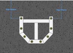
7,The edge distance and spacing should not be less than the specified values as per the bollard manufacturer’s calculations.
8,The anchor hole should be hammer-drilled with a diamond core drill bit.
9,If the drill hole is aborted, the hole should be filled with mortar.
10,For an overhead installation, piston plugs must be used. Embedded metal parts must be fixed during the curing time, e.g. with wedges.
11,For injection of the mortar in bore holes ≤250 mm, piston plugs must be used.
CAST-IN ANCHOR INSTALLATION
Anchors need to be installed at their designated position before the concrete is poured. Steel reinforcements have to be provided to the anchors.
MATERIALS/CONSUMABLES REQUIRED | INFORMATION |
Reinforced concrete block | With adequate compressive strength |
Steel reinforcement bar | Used to anchor template/Cage Hold Down Bolts |
EQUIPMENT REQUIRED | INFORMATION |
Anchors | Supplied by Supplier |
Anchor bolt template | Supplied by Supplier |
Spanner | Suitable to the supplied anchor size |
RECOMMENDED PERSONAL PROTECTIVE EQUIPMENT | INFORMATION |
General PPE | As per site/plant requirements |
CAST-IN ANCHORS need to be installed at their designated position before the concrete is poured. Steel reinforcements have to be provided to the anchors.
Step 1. Mark embedment length on all anchors used for each bollard.

Step 2. Use two anchor templates to locate and align the anchors vertically straight.

1,As shown in the image, place one anchor template on the head of the anchor and fix another template below the marking of the embedment length.
2,Restrain the top template temporarily to avoid any movement.
3,Reinforce the anchors with steel bars as per ACI318.11. The reinforcement design can be carried out by a jetty designer.
Step 3. Start pouring the concrete as per the instruction of the supervisor.
Note:In the case of a recess mounted bollard, use a cover boundary to stop the concrete being poured on the required recess for the bollard.
Step 4. Provide enough time to cure the concrete.
Note :
1,Do not touch the anchors until the desired curing time required for the concrete has passed.
2,Check the required protrusion height of each anchor.
Step 5. After pouring, use the template to check the final anchor locations as per the relevant drawings.

EPOXY/RESIN ANCHOR INSTALLATION
Fully threaded anchors are used with resin/epoxy bond materials to achieve a bond between the anchors and the existing concrete. The detailed 5 step procedure is as follows:
Step 1. Marking
①,Clean the area first and use an anchor template to mark the positions of the holes on the jetty surface. Use a marker pen to highlight the marked holes.
②,Measure the distance from the jetty edge to the first anchor as per the drawings.
③,Clean the area again and measure each distance to be verified with the bollard drawing.
Step 2. Drilling/Coring

1,Set the drilling machine in such a way that the drill bit axis and the center of the marking hole are aligned.
2,Use a bubble gauge meter to verify that the drill bit is perfectly vertical.
3,Use a continuous flow of water to reduce heat generation between the drill bit and the concrete.
4,Slowly drill the hole up to the required depth.
Note :
1,Marking on the drill bit helps to determine the depth of the hole. Diamond coring is permissible when a diamond core drilling machine and the corresponding core bit are used.
2,Verify that the depth and diameter of the holes are within the tolerance ranges mentioned in the relevant anchor layout drawing.
3,Once the hole has been cored to the desired depth and diameter, roughen the surface of the core hole using a rotary hammer drill bit. (Roughing the surface of the hole is a recommendation and not a requirement.)
Step 3. Cleaning

1,Starting from the bottom surface of each hole, use a pressurised water flow to clean the holes.
2,Run a flow of water continuously into the holes until the water runs out clear.
3,Brush two times with the specified brush size (brush Ø ≥ bore hole Ø, see Table 7 in Hilti manual) by inserting the steel brush (Hilti HIT-RB or equivalent) to the back of the hole (use an extension if needed) in a twisting motion and removing it.
4,The brush must produce natural resistance as it enters the bore hole.
5,Blow oil-free compressed air (with min. 6bar / 90 psi pressure) two times inside the drilled hole, starting from the bottom surface of the hole (use a nozzle extension if needed) over the hole length until the return air stream is free of noticeable dust and water.
6,Alternate the cleaning by water and air two more times.
Step 4. Injection

1,Insert foil pack in foil pack holder. Do not use damaged foil packs and/or damaged or unclean foil pack holders. Attach new mixer prior to dispensing a new foil pack (snug fit).
2,Tightly attach Hilti(HIT-RE-M) or equivalent mixer to foil pack manifold. Do not modify the mixer in any way. Make sure the mixing element is in the mixer. Use only the mixer supplied with the adhesive.
3,Insert foil pack holder with foil pack into HIT-dispenser. Push release trigger, retract plunger and insert foil pack holder into the appropriate Hilti dispenser.
4,Discard initial adhesive. The foil pack opens automatically as dispensing is initiated. Depending on the size of the foil pack an initial amount of adhesive must be discarded.
5,Discard quantities are 3 strokes for 330 ml foil pack, 4 strokes for 500 ml foil pack and 65 ml for 1400 ml foil pack.
6,Inject adhesive start from the bottom of the bore hole without forming air voids. Slowly withdraw the mixer with each trigger pull.
7,Continue filling the bore hole either up to recommended amount of adhesive or until hole fills 2/3 full.
8,It is required to ensure that the annular gap between the anchor and the concrete is filled with adhesive along the embedment length.
Step 5. Setting anchors
1,Before use, clean each anchor with water and dry them completely with oil-free air. Verify that the element is dry and free of oil and other contaminants.
2,Anchors must be twisted slowly and inserted into the core, which is filled with epoxy/ resin.
3,Mark and set the element to the required depth until working time has elapsed. The working time is given in the table below.
TEMPERATURE IN | MAX.WORKING | MIN. CURING TIME |
5 to 9 | 120 | 72 |
10 to 14 | 90 | 48 |
15 to 19 | 30 | 24 |
20 to 29 | 20 | 12 |
30 to 39 | 12 | 8 |
40 | 12 | 4 |


