
Views: 425 Author: Nanjing Taidun Publish Time: 2026-05-13 Origin: Site
Content Menu
● What Is a Marine Fender Steel Frontal Panel?
● PIANC Guidelines: The Foundation of Frontal Panel Design
>> The Transition from WG33 to WG211 (2024)
● Core Design Principles for Steel Frontal Panels
>> Principle 1 — Load Distribution and Hull Pressure Limits
>> Principle 2 — PIANC Hull Pressure Limits by Vessel Type
>> Principle 3 — Minimum Steel Thickness Requirements
>> Principle 4 — Panel Geometry and Stiffening
>> Principle 5 — Corrosion Protection Systems
● Advanced Design Considerations
>> Finite Element Analysis (FEA) for Stress Optimization
● PIANC WG211 Updates Affecting Frontal Panel Design
>> Multiple Fender System Contact
>> Base Fender Performance Terminology
● How Nanjing Taidun Supports Frontal Panel Design
● Frequently Asked Questions (FAQ)
When a container ship weighing over 100,000 tons approaches a berth, the only thing standing between a safe stop and catastrophic damage is a marine fender steel frontal panel. This steel structure distributes millions of kilonewtons of impact force across the vessel's hull—protecting both the ship and the quay wall.
But a poorly designed frontal panel can cause hull puncture, premature fender failure, or costly structural damage.
I have spent two decades manufacturing OEM marine fender systems for global brands. In this guide, I will walk you through the design principles for marine fender steel frontal panels based on PIANC Guidelines, engineering best practices, and real-world project data—including the updated PIANC WG211 (2024) framework.
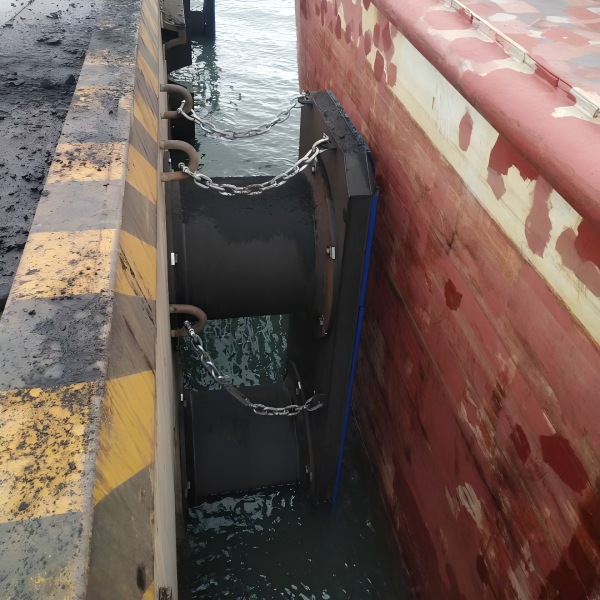
A frontal panel—also known as a frontal frame or steel facing panel—is the rigid steel structure mounted on the face of a rubber fender .
| Component | Function |
|---|---|
| Steel panel body | Distributes impact forces across vessel hull |
| UHMW-PE facing pad | Reduces friction; protects hull from steel contact |
| Mounting brackets | Connects panel to rubber fender units |
| Stiffeners | Prevents panel deformation under load |
> *"Frontal panels are critical to the correct performance of the fender system. They distribute the reaction forces to the hull of berthing vessels."*
The panel is the direct interface between the fender system and the vessel. Without it, the concentrated force of a rubber fender could exceed hull pressure limits—damaging or even puncturing the ship's side shell.
The International Navigation Association (PIANC) provides the industry-standard guidelines for fender system design. For nearly two decades, PIANC WG33 (2002) was the definitive reference .
In April-May 2024, PIANC published WG211 – PIANC Fender Guidelines 2024, replacing the previous WG33 .
| Aspect | WG33 (2002) | WG211 (2024) |
|---|---|---|
| Safety approach | Global safety factor | Partial resistance factors |
| Multiple fender contact | Simplified treatment | Dedicated correction factor |
| Hull pressure guidance | Basic tables | Expanded vessel categories |
| Base Fender Performance | Not defined | New terminology introduced |
> *"PIANC WG211 introduces the term 'Base Fender Performance'… including a new correction factor associated with accounting for the effect of multiple fender system contacts and the application of partial resistance factors."*
For frontal panel designers, the key updates include:
- Expanded hull pressure tables for modern vessel types
- Guidance on multiple fender contact (berthing angles affecting panel loading)
- Updated methodology for calculating required panel dimensions
The most critical design principle is ensuring the panel distributes impact forces so that hull pressure remains below vessel-specific limits .
Formula for hull pressure calculation:
> P = ΣR / (A₁ × B₁) ≤ Pₚ
Where:
- P = Actual hull pressure
- ΣR = Combined reaction forces of all rubber fenders
- A₁ = Valid panel width (excluding lead-in chamfers)
- B₁ = Valid panel height (excluding lead-in chamfers)
- Pₚ = Permissible hull pressure
PIANC provides the following permissible hull pressure guidelines :
| Vessel Type | Permissible Hull Pressure (kN/m²) |
|---|---|
| Container vessels 1st & 2nd gen | < 400 |
| 3rd gen (Panamax) | < 300 |
| 4th gen | < 250 |
| 5th & 6th gen (Post-Panamax) | < 200 |
| General cargo (<20,000 DWT) | 400–700 |
| General cargo (>20,000 DWT) | < 400 |
| Oil tankers (<60,000 DWT) | < 300 |
| Oil tankers (>60,000 DWT) | < 350 |
| VLCC | < 350 |
| LNG/LPG gas carriers | < 200 |
| Bulk carriers | < 200 |
> *"According to PIANC guidelines, frontal panels should keep surface pressure below 200 kN/m² when berthing large vessels."*
Why This Matters: Exceeding these limits can cause hull deformation, paint damage, or structural failure of the vessel's side shell.
PIANC specifies minimum steel thicknesses for frontal panels based on corrosion exposure :
| Exposure Condition | PIANC Recommended Minimum Thickness |
|---|---|
| Plates exposed on two surfaces (tidal zone) | 12 mm |
| Plates exposed on one surface | 9–10 mm |
| Internal members (not exposed) | 8 mm |
These thicknesses account for:
- Corrosion wastage over the fender's design life (typically 25+ years)
- Structural integrity under repeated impact loading
- Welding heat effects that can reduce local strength
Panel geometry directly affects load distribution and weight.
Closed-Box Panels (most popular for large terminals) :
- Front and back plates with internal stiffeners
- Fully welded, sealed perimeter
- Superior torsional rigidity
- Enhanced corrosion protection (sealed interior)
Open Frame Panels:
- Structural members with open spaces
- Lighter weight, lower cost
- All surfaces exposed to corrosion
- Suitable for low-energy berths
Stiffener Design Considerations:
- Vertical and horizontal stiffeners prevent panel buckling
- Stiffener spacing based on FEA analysis
- Connection details must allow load transfer to rubber fenders
Marine environments are extremely corrosive. Steel panels require robust protection .
| Protection Method | Application | Expected Life |
|---|---|---|
| Epoxy coating system | Tidal/splash zones | 10–15 years |
| Thermal-sprayed aluminum | High-exposure areas | 15–20 years |
| Cathodic protection | Submerged components | 20+ years |
| Stainless steel (316/duplex) | Critical hardware | 25+ years |
> *"Marine-grade steels like AH36, DH36 or stainless steel variants provide the necessary strength-to-weight ratios and corrosion resistance."*
Inspection Access: Design must include access points for regular coating inspection and maintenance .
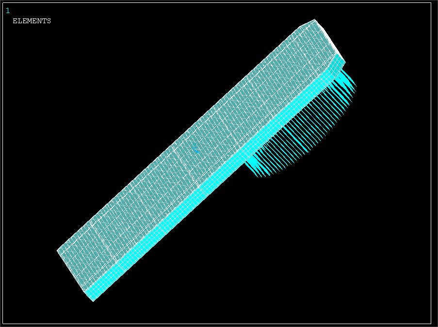
Modern frontal panel design relies on Finite Element Analysis (FEA) to validate structural integrity before fabrication .
FEA evaluates:
- Stress distribution under peak impact loads
- Deflection limits to prevent bottoming out
- Fatigue life for high-cycle berths
- Buckling resistance in thin sections
> *"Modern marine fender frontal panel design incorporates Finite Element Analysis (FEA) for stress distribution optimization."*
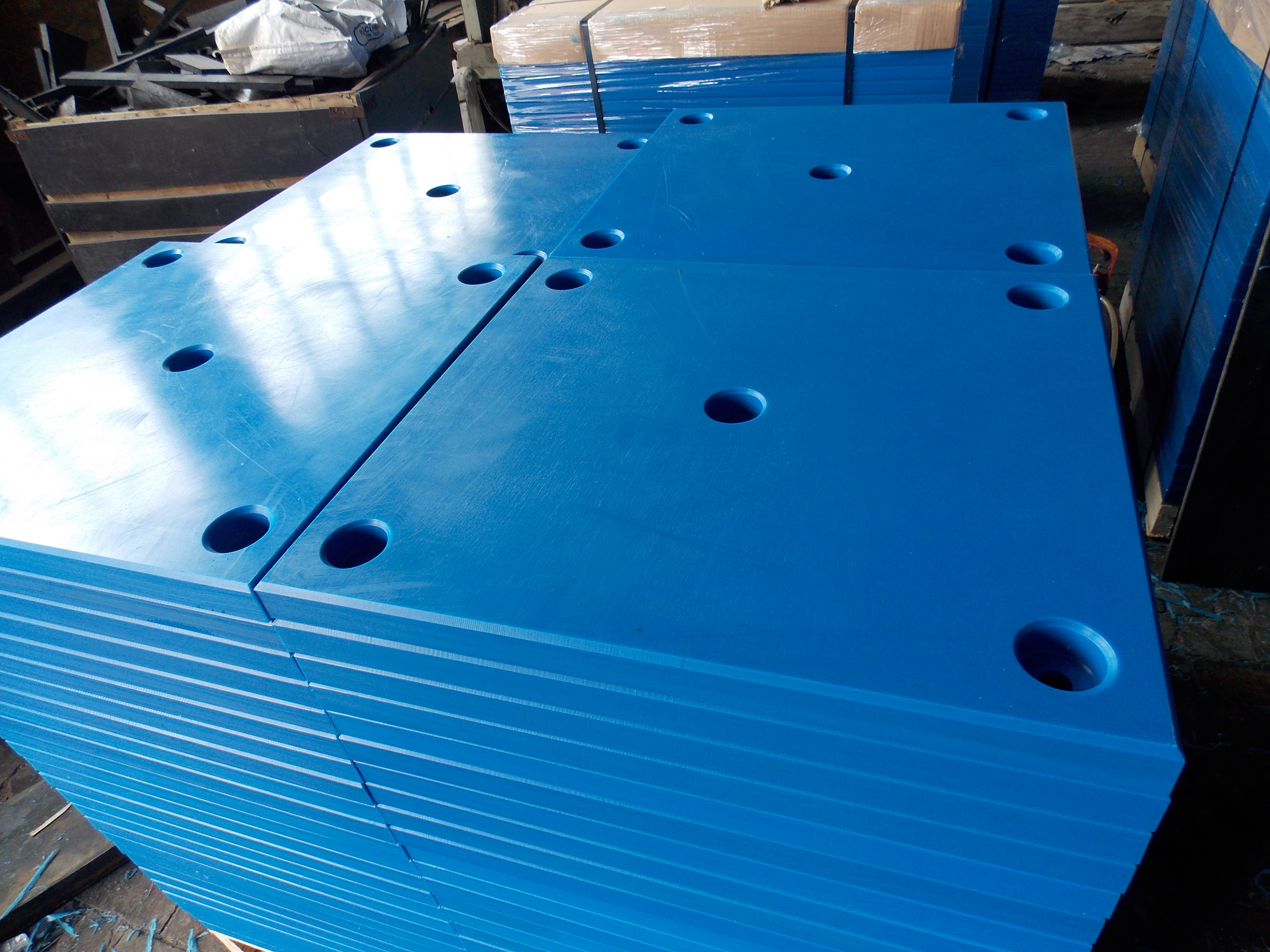
Most frontal panels include Ultra-High Molecular Weight Polyethylene (UHMW-PE) facing pads .
Advantages:
- Low friction coefficient (reduces hull abrasion)
- High wear resistance
- Self-lubricating properties
- Protects steel from direct vessel contact
Frontal panels require lead-in chamfers at the edges to prevent snagging during off-angle berthing .
- Chamfers prevent hull damage during angled approaches
- They are excluded from valid panel area (A₁ × B₁) for hull pressure calculations
- Typical chamfer width: 200–400 mm per side
The transition to WG211 (2024) introduces several changes relevant to frontal panel design .
WG211 adds a new correction factor for multiple fender contacts—critical for panels used in fender arrays.
> *"WG211 includes a new correction factor associated with accounting for the effect of multiple fender system contacts."*
Design implication: Frontal panels must be sized to accommodate simultaneous compression of multiple fender units during off-center berthing.
WG211 replaces the old global safety factor with partial resistance factors for different failure modes .
Design implication: Panel designs must consider separate safety factors for:
- Steel yielding
- Weld failure
- Buckling
- Corrosion wastage
WG211 introduces Base Fender Performance as a standardized reference point for fender selection .
Design implication: Frontal panel dimensions must be matched to the base performance of the selected rubber fenders—accounting for velocity, temperature, and angle correction factors.
We asked our global OEM clients about their experience with frontal panel design. Here is what they shared:
> *"We used to spec open-frame panels for our container terminal. After five years, corrosion had compromised the structure. We switched to closed-box panels with sealed interiors. Seven years later, they still look like new."*
> — *Terminal Engineer, Southeast Asian Port*
> *"The PIANC hull pressure tables saved us from a costly mistake. We were about to install panels that would have exceeded the 200 kN/m² limit for our post-Panamax vessels. Redesigning the panel width solved the problem."*
> — *Project Manager, European Port Authority*
> *"Our biggest lesson: don't skimp on steel thickness. A supplier offered 8mm plates for a tidal zone application. PIANC requires 12mm minimum for two-side exposure. We paid more upfront—but ten years later, those panels are still sound."*
> — *Maintenance Director, Middle East Terminal*
At Nanjing Taidun Marine Equipment Engineering Co., Ltd. , we manufacture PIANC-compliant steel frontal panels for marine fender systems.
Our capabilities include:
| Service | Description |
|---|---|
| Custom fabrication | Closed-box or open-frame; any dimensions |
| Material selection | Marine-grade steels (AH36, DH36, 316 stainless) |
| Coating systems | Epoxy, thermal-sprayed aluminum, cathodic protection |
| UHMW-PE facing | Custom thickness and attachment methods |
| FEA validation | Stress, deflection, and fatigue analysis |
| Third-party certification | ABS, BV, DNV, LR, CCS available |
We serve brand owners, wholesalers, and production facilities in over 80 countries. When you partner with Taidun, you get PIANC-compliant design, certified materials, and full engineering documentation.
Designing marine fender steel frontal panels requires understanding PIANC guidelines, vessel hull pressure limits, minimum steel thicknesses, corrosion protection, and the latest WG211 (2024) updates.
A properly designed panel:
- Keeps hull pressure below 200–350 kN/m² (depending on vessel)
- Uses minimum 12mm steel in tidal zones
- Incorporates closed-box construction for high-energy berths
- Includes UHMW-PE facing and lead-in chamfers
[Contact the Nanjing Taidun Engineering Team] for a free frontal panel design consultation. Send us your berthing energy requirements and vessel mix, and we will recommend the optimal panel configuration for your application.
Q1: What is the minimum steel thickness for marine fender frontal panels per PIANC?
A: PIANC recommends 12mm minimum for plates exposed to seawater on both surfaces (tidal zone), 9–10mm for one-side exposure, and 8mm for internal members not exposed to corrosion .
Q2: What is the maximum allowable hull pressure for large container vessels?
A: For 5th and 6th generation (Post-Panamax) container vessels, PIANC specifies hull pressure below 200 kN/m². VLCCs, LNG carriers, and bulk carriers have similar limits .
Q3: What is the difference between closed-box and open-frame frontal panels?
A: Closed-box panels have front/back plates with sealed interiors—superior rigidity and corrosion protection, ideal for high-energy terminals. Open-frame panels are lighter and cheaper but expose all surfaces to corrosion .
Q4: How has PIANC WG211 (2024) changed frontal panel design?
A: WG211 introduces partial resistance factors, a new correction factor for multiple fender contacts, and expanded hull pressure guidance. Designers must now account for these factors in panel sizing .
Q5: Why are UHMW-PE facing pads used on frontal panels?
A: UHMW-PE provides a low-friction, high-wear-resistant surface that protects the vessel hull from direct steel contact and reduces abrasion damage during berthing .
1. Williams, R., Roubos, A.A., Oskamp, J., Lamont Smith, B., & Nyvoll, S.O. (2024). *Fender System Selection in PIANC WG211*. In: Proceedings of the 35th PIANC World Congress 2024, pp. 732-739. [https://research.tudelft.nl/en/publications/fender-system-selection-in-pianc-wg211/]
2. Nanjing Taidun Marine Equipment Engineering Co., Ltd. (2026). *The Ultimate Guide To Frontal Panel for Marine Rubber Fender*. [https://www.taidunmarine.com/the-ultimate-guide-to-frontal-panel-for-marine-rubber-fender-engineering-expertise-real-world-performance-maintenance-innovation.html]
3. Nanjing Taidun Marine Equipment Engineering Co., Ltd. (2026). *Marine Fender Steel Frontal Panel: Design Essentials and Key Considerations*. [https://www.taidunmarine.com/marine-fender-steel-frontal-panel-design-essentials-and-key-considerations.html]
4. PIANC. (1998). *Life cycle management of port structures – general principles* (MarCom WG 31). [https://www.pianc.org/publication/life-cycle-management-of-port-structures-general-principles/]


