


Views: 376 Author: NANJING TAIDUN Publish Time: 2026-09-21 Origin: Site
Content Menu
● What Is a Whole System Approach to Fender Performance?
● The Hidden Cost of Component-Level Procurement
● Application Engineering: The Foundation of System Performance
>> Berthing Energy Calculation: More Than a Formula
>> Correction Factors: Where Systems Succeed or Fail
● Detailed System Design: The Components That Make or Break Performance
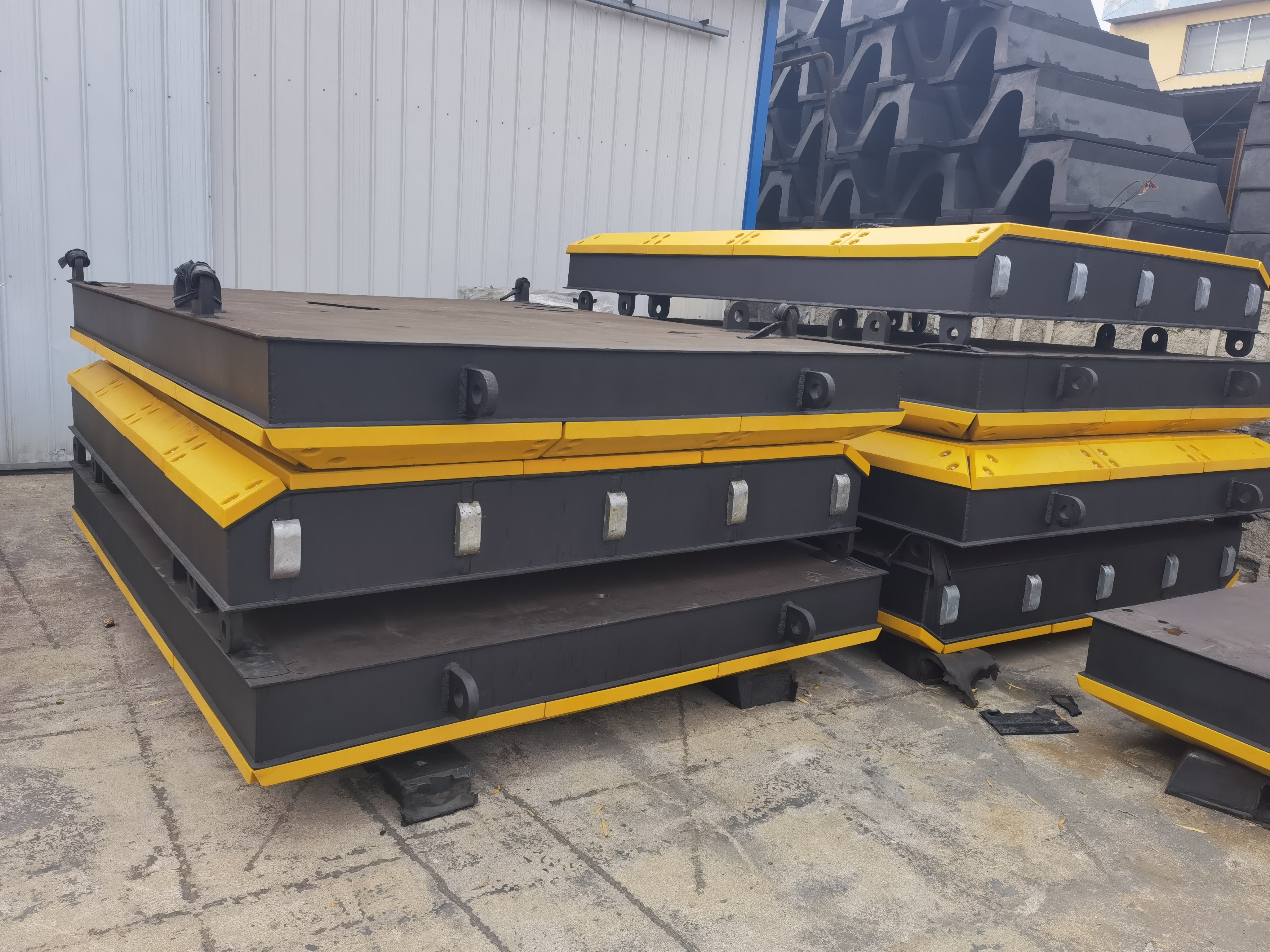
>> The Frontal Panel: More Than a Steel Plate
>> UHMW-PE Facings: The Science of Low Friction
>> Chain Systems: The Unsung Hero of Fender Performance
● Production and Quality Control: Where Specifications Become Reality
>> The PIANC 2024 Standard Update
>> Testing Protocol: Beyond the Compression Test
● Installation, Operations, and Maintenance: The Long Tail of Performance
>> Installation Considerations That Affect Long-Term Performance
>> Proactive Inspection: Identifying Degradation Before Failure
● Real-World Case: Whole System Approach in Action
>> North American Jetty Upgrade: Parallel Motion Fenders
● OEM Implications: What Brand Owners and Wholesalers Should Demand
>> The Traceability Imperative
● Conclusion: Systems Thinking for Port Infrastructure
● Frequently Asked Questions (FAQ)
>> 1. What is the difference between a fender component and a fender system?
>> 2. Why is PIANC 2024 compliance important for fender procurement?
>> 3. What correction factors affect fender performance in real-world conditions?
>> 4. Why is UHMW-PE used for fender panel facings?
>> 5. What documentation should OEM partners request from fender manufacturers?
>> 6. How does the Parallel Motion Fender (PMF) demonstrate the whole system approach?
Introduction
The global port industry is at an inflection point. Vessels are getting larger, cargo volumes are surging, and environmental regulations are tightening across every major maritime jurisdiction. Ports that once focused on procuring individual fender units are now discovering that component-level purchasing often leads to system-level failure.
As an OEM manufacturer at NANJING TAIDUN MARINE EQUIPMENT ENGINEERING CO., LTD, we have witnessed this shift firsthand. Our partners—brand owners, wholesalers, and manufacturers across Europe, Southeast Asia, and the Americas—are increasingly asking not just for rubber fenders, but for complete, tested, traceable fender systems.
This article examines why the whole system approach has become the industry benchmark, and what it means for OEM procurement strategies.
A whole system approach treats the fender not as a standalone rubber product, but as an integrated engineering solution that spans four critical phases:
1. Application Engineering – Analyzing berthing data, site conditions, and vessel characteristics
2. Detailed System Design – Engineering the complete assembly including panels, chains, and fixings
3. Production & Quality Control – Manufacturing components to verified specifications
4. Installation, Operations & Maintenance – Ensuring long-term performance in real-world conditions
The failure to address any one of these phases creates a weak link that undermines the entire system.
> *"Taking a whole system approach to fender systems will reduce construction costs, downtime and operating expenditure... In short, a fender system that lasts longer and offers enhanced reliability—and that requires less maintenance—is both a better investment and better for the environment."
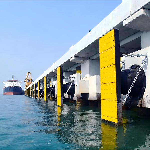
Many ports and contractors still procure fender components separately: rubber units from one supplier, steel panels from another, chains from a third. This fragmented approach appears cost-effective on paper. In practice, it creates a cascade of hidden costs.
When components are sourced independently, interface compatibility is assumed rather than engineered. A chain rated for a certain load may not match the reaction force characteristics of the rubber fender it is paired with. A panel designed for one fender pitch may not distribute loads correctly across a different configuration.
The result: premature wear, unexpected failures, and warranty disputes.
Component-level procurement also fragments accountability. When a failure occurs, determining whether the rubber, the panel, the chain, or the installation caused the problem becomes an expensive forensic exercise.
A whole system approach eliminates this ambiguity by establishing a single chain of responsibility from design to commissioning.
Application engineering is where the whole system approach begins—and where the greatest value is created.
The fundamental requirement is straightforward: the energy absorption capacity of the fender system must exceed the berthing energy of the design vessel.
But berthing energy is not a fixed number. It depends on:
- Vessel displacement and approach velocity
- Berthing angle (angular factor)
- Temperature conditions (temperature factor)
- Eccentricity of impact (eccentricity factor)
A fender that performs adequately at 0° berthing may lose 50% or more of its energy absorption capacity at 20° approach angles.
The fender performance published in a catalog represents idealized conditions. Real-world performance requires the application of correction factors:
| Factor | Impact on Performance | Typical Consideration |
|---|---|---|
| Angular Factor | Significant reduction at angled berthing | Vessel berthing patterns |
| Temperature Factor | Rubber stiffens in cold, softens in heat | Local climate extremes |
| Velocity Factor | Higher speeds demand more capacity | Tidal and current conditions |
The critical insight: A fender selected without correction factors is a fender selected for conditions that do not exist.
> *"Berthing factors such as angular factor, temperature factor, and velocity factor need to be considered during the selection of a fender, and data should be backed up with testing documents and published in a catalog. Applying the right performance correction factors is vital to overall fender performance."*
Once application engineering establishes the performance envelope, detailed system design translates it into physical hardware.
The frontal panel serves three critical functions:
1. Load distribution – Spreads reaction force across the vessel hull
2. Friction management – Houses UHMW-PE facings to allow controlled vessel movement
3. Accessory integration – Provides mounting points for chains, ladders, and maintenance access
Panel design considerations:
- Maximum reaction force tolerance
- Low-friction facing pad selection
- Restraining chain design
- Corrosion protection systems
- Fastening system compatibility
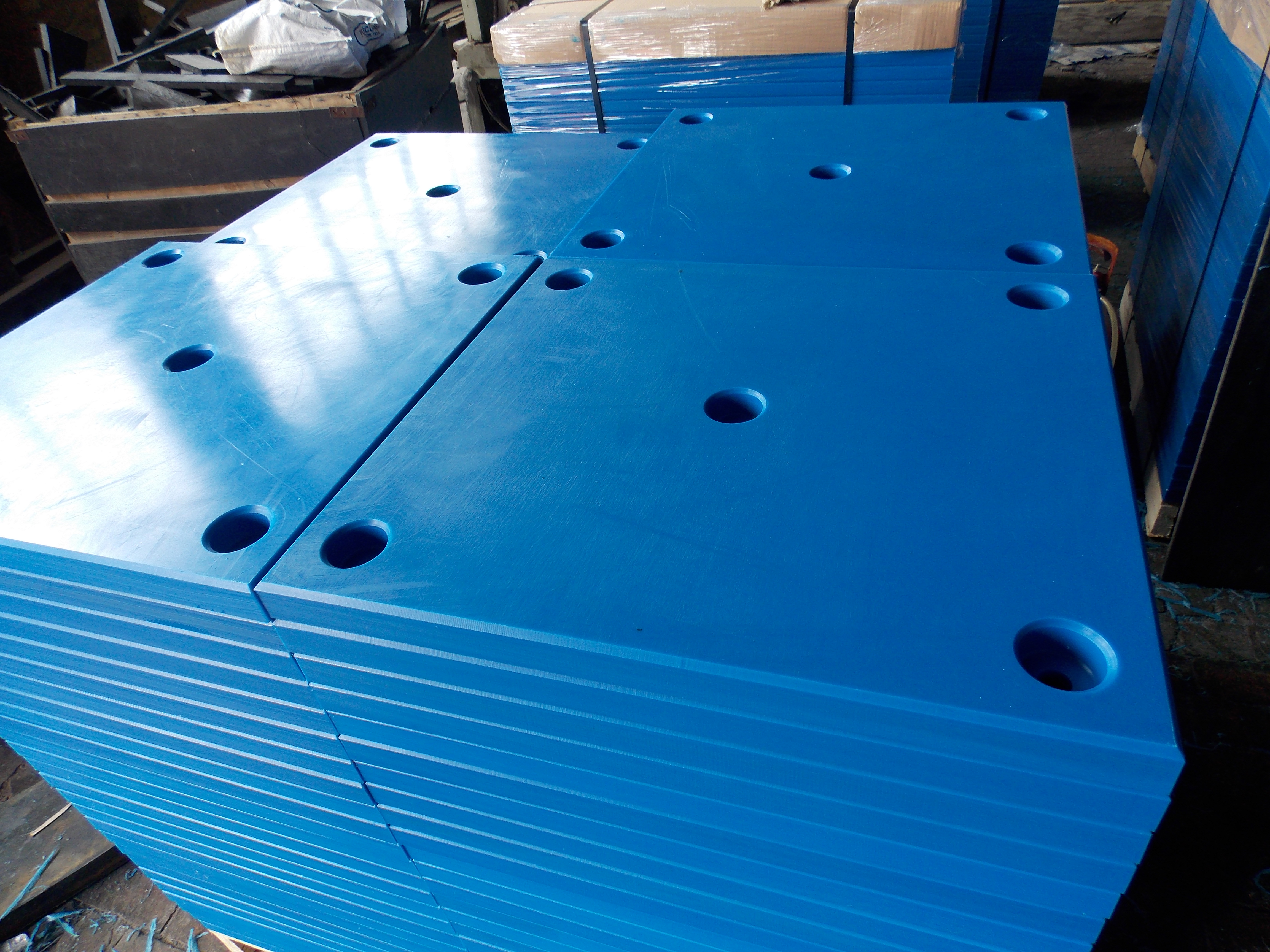
Ultra-High Molecular Weight Polyethylene (UHMW-PE) is the industry-standard facing material for fender panels. Its properties explain why:
| Property | Value | Performance Benefit |
|---|---|---|
| Friction Coefficient | 0.15–0.2 (PE-Steel) | Enables controlled vessel movement |
| Abrasion Resistance | Excellent | Extended service life |
| Impact Strength | High | Withstands direct contact |
| UV/Ozone Resistance | Excellent | Marine environment durability |
Critical design note: PIANC 2024 guidelines recommend using a minimum coefficient of friction of 0.3 for designing supporting structures and chains—even if the facing material is rated lower—to account for wear, contamination, and contact pressure effects.
Chains do more than restrain the fender. They manage shear forces, control panel movement, and protect the rubber units from excessive deformation.
Chain design parameters:
- Safe Working Load (SWL) calculation based on reaction force, friction coefficient, and chain geometry
- Minimum Breaking Load (MBL) with safety factor of 2–3 (typically)
- Material specification: Typically CM490 anchor chain steel with hot-dip galvanizing (≥100μm thickness)
The chain design formula accounts for a friction coefficient of 0.2 between the UHMW-PE facing and steel vessel hull.
A well-designed system means nothing if production fails to meet design intent. Quality control is not a department—it is a process embedded at every production stage.
PIANC Working Group 211 released updated fender guidelines in 2024, with compliance required by May 1, 2026. Key changes include:
- Stronger focus on system testing rather than component testing alone
- Revised berthing physics (higher velocities, lower angles, multiple contacts)
- Greater emphasis on site-specific design data
- More stringent material quality requirements
What this means for OEM partners: Fender catalogs must be updated, test protocols revised, and manufacturing processes validated against the new standard.
While compression testing (reaction force and energy absorption) remains fundamental, a whole system approach demands broader verification:
| Test Category | Scope | Documentation |
|---|---|---|
| Rubber Compound | Tensile strength, elongation, hardness, ozone resistance | Material certificates |
| Compression Performance | Energy absorption, reaction force at rated deflection | Test reports per batch |
| Coating Systems | Steel panel and chain corrosion protection | Thickness measurements |
| Assembly Verification | Dimensional accuracy, component fit | Inspection records |
Third-party witnessing (BV, SGS, ABS, LR, DNV) provides independent verification that documented performance matches delivered product.
A fender system that performs perfectly in the factory can fail within months if installation is flawed or maintenance is neglected.
Design for maintenance access begins at the engineering stage. If panels cannot be accessed for facing replacement, or chains cannot be adjusted, the system's service life is determined by its least accessible component.
Handling and storage also affect outcomes. Damaged coatings during unloading, improper storage that exposes UHMW-PE to UV degradation, or mishandling of chains all create problems that emerge months later.
PIANC guidance emphasizes scheduled inspection as a core maintenance practice. Key degradation indicators include:
- Rubber: Cracks, tears, permanent deformation, ozone cracking
- Panels: Coating breakdown, corrosion, facing pad wear
- Chains: Link wear, corrosion, tension loss
- Anchors: Bolt loosening, corrosion at embedment
A structured inspection program converts reactive repairs into planned maintenance—reducing downtime and extending asset life.
The value of a whole system approach becomes clearest when examining actual project outcomes.
Challenge: An aging jetty needed to accommodate larger vessels but could not support major structural modification. Tidal range of approximately 8.8 meters complicated berthing operations.
Solution: A Parallel Motion Fender (PMF) system with back-to-back Super Cone fenders in vertical series. The design included:
- Two sets of SCN800 cone fenders (one hard compound, one soft)
- 10.9m × 3.05m frontal panel
- Torsion tube and arm assembly
- Reaction force reduction of up to 60%
Outcome: The system absorbed twice the energy of conventional cone fenders while maintaining low reaction forces on the existing structure. The non-tilt design kept the panel vertical at all impact points, accommodating large berthing angles without performance loss.
Key takeaway: The whole system approach enabled a solution that no individual component could deliver.
For OEM partners sourcing fender systems for their markets, the whole system approach translates into specific procurement requirements.
1. System-level performance data – Not just rubber unit ratings, but complete assembly performance
2. Correction factor documentation – Published data on angular, temperature, and velocity factors
3. Component traceability – Material certificates for rubber, steel, and chains
4. Test report packages – Compression tests, material tests, coating thickness measurements
5. Third-party certification – BV, SGS, ABS, or equivalent witnessing
6. Installation and maintenance documentation – Including handling procedures and inspection guidelines
As an OEM manufacturer, we understand that our partners' reputations depend on our quality. Every component we produce is traceable to its source batch—from the rubber compound formulation to the steel mill certificate for chains and panels.
This is not optional. It is the foundation of trust in international OEM partnerships.
The whole system approach to fender performance is not a marketing concept. It is an engineering philosophy grounded in the recognition that components do not exist in isolation.
A rubber fender without a properly designed panel is a liability. A panel without correctly specified chains is a failure waiting to happen. Chains without proper installation and maintenance are an accident in progress.
For port authorities, terminal operators, and OEM partners, the implication is clear: procure systems, not parts. Verify performance, not just specifications. And demand traceability from raw material to installed asset.
At NANJING TAIDUN, we manufacture fender systems—not just rubber fenders. Our OEM partners receive the full package: application engineering support, system design, production quality control, and comprehensive documentation.
Ready to discuss whole system fender solutions for your market?
Contact NANJING TAIDUN MARINE EQUIPMENT ENGINEERING CO., LTD:
- Email: service@taidunmarine.com
- Website: www.taidunmarine.com
- OEM Services: System design, custom rubber compounding, third-party testing coordination, full documentation packages
1. PIANC WG 211. "Berthing Velocity, Fender Reaction Force, and Chain Design." [https://www.kscoe.or.kr/!/download/?path=/media/51/board/2025/01/31/7._PIANC_MarCom_WG_211.pdf]
2. Riviera Maritime Media. "New global fender standards come into force in May." [https://www.rivieramm.com/lead-stories-brand/new-global-fender-standards-come-into-force-88507]
3. PIANC. "Fender Inspection – Looking for Signs of Deterioration and Degradation of Marine Fender Systems." [https://pianc.pt/wp-content/uploads/2023/10/Artigo-45.pdf]
4. TUDelft. "Fender System Selection in PIANC WG211." [https://pure.tudelft.nl/ws/portalfiles/portal/221661024/Fender_System_Selection_in_PIANC_WG211.pdf]
A component is an individual element—a rubber fender unit, a steel panel, or a chain. A system is the complete, engineered assembly of components designed to work together, including application engineering, detailed design, production quality control, installation, and maintenance planning. Component-level procurement often leads to interface incompatibilities and undefined accountability when failures occur.
PIANC WG211 released updated fender guidelines in 2024, with full compliance required by May 1, 2026. These updates include revised berthing physics models, stronger system testing requirements, and more stringent material standards. Ports and OEM partners should verify that suppliers have updated their catalogs and test protocols to meet the new guidelines.
Three primary factors reduce published fender performance in actual operations:
- Angular factor – Energy absorption can decrease significantly at berthing angles above 0°
- Temperature factor – Rubber stiffens in cold conditions (higher reaction force) and softens in heat (lower energy absorption)
- Velocity factor – Higher berthing speeds demand greater energy capacity
Designers must apply these factors to select fenders that perform as intended.
UHMW-PE (Ultra-High Molecular Weight Polyethylene) offers an optimal combination of properties:
- Low friction coefficient (0.15–0.2 against steel) – allows controlled vessel movement during berthing
- Excellent abrasion resistance – withstands repeated vessel contact
- Non-marking – does not damage vessel paint
- Seawater and UV resistance – suitable for marine environments
PIANC recommends using a minimum friction coefficient of 0.3 for designing supporting structures to account for wear and contamination.
A complete documentation package should include:
- Product certificate of conformity
- Original design drawings and modification records
- Compression test reports (reaction force and energy absorption per batch)
- Material certificates for rubber compound and steel components
- Coating thickness measurements for panels and chains
- Third-party inspection reports (BV, SGS, ABS, or equivalent)
- Installation, handling, and maintenance manuals
Traceability from raw material to finished product is essential for quality assurance and liability protection.
The PMF system integrates multiple components—back-to-back Super Cone fenders, a torsion tube assembly, a closed-box panel with UHMW-PE facings, and hinge units—into a single engineered solution. This integration delivers performance that no individual component could achieve: reaction force reduction of up to 60% while maintaining double the energy absorption of conventional fenders. It exemplifies why system-level design and testing are essential.


