

Views: 253 Author: Nanjing Taidun Publish Time: 2026-11-10 Origin: Site
Content Menu
● Cast Steel vs Forged Steel Chocks: Which Lasts Longer?
● What "24/7 Mooring Cycles" Actually Means
>> Count Stress Cycles, Not Ship Visits
>> Distinguish Shipboard and Shore-Side Applications
● Why Manufacturing Quality Changes Fatigue Performance
>> Cast Steel Chocks: Control Solidification and Critical Sections
>> Forged Steel Chocks: Verify the Claimed Advantage
● The Fatigue Weak Link May Be Outside the Chock Body
● How to Estimate Chock Fatigue Life Responsibly
>> Step 1: Define the Load Spectrum
>> Step 2: Calculate Local Stress Ranges
>> Step 3: Select Applicable Fatigue Data
>> Step 4: Assess Cumulative Damage
● Worked Example: Why Lower Stress Can Matter More Than the Label
● An OEM Procurement Checklist for Overseas Buyers
>> Send a Complete Technical Enquiry
>> Define Inspection Before Production
>> Compare Total Ownership Cost
● Inspection Planning for Continuous Mooring Service
● Specify the Requirement Before Selecting the Manufacturing Route
>> 1. Do forged steel chocks always last longer than cast steel chocks?
>> 2. How many years should a continuously used mooring chock last?
>> 3. Does a static proof test demonstrate fatigue life?
>> 4. Can a higher steel strength solve a fatigue problem?
>> 5. What records should OEM buyers prioritize?
>> 6. When should an existing chock receive additional assessment?
At Nanjing Taidun Marine Equipment Engineering Co.,Ltd, we serve overseas brands, wholesalers, and manufacturers through OEM marine equipment manufacturing. For buyers comparing cast steel vs forged steel chocks, fatigue life expectancy under 24/7 port mooring cycles should be evaluated through the complete load path—not the manufacturing label alone.
A properly manufactured forging can offer advantages in material integrity and directional properties. However, a well-designed steel casting can also provide dependable service. Neither route supports a universal promise of ten, twenty, or thirty years without application-specific evidence.
Our procurement perspective is straightforward: specify the operating conditions, identify the fatigue-critical details, and compare documented manufacturing quality before comparing prices.
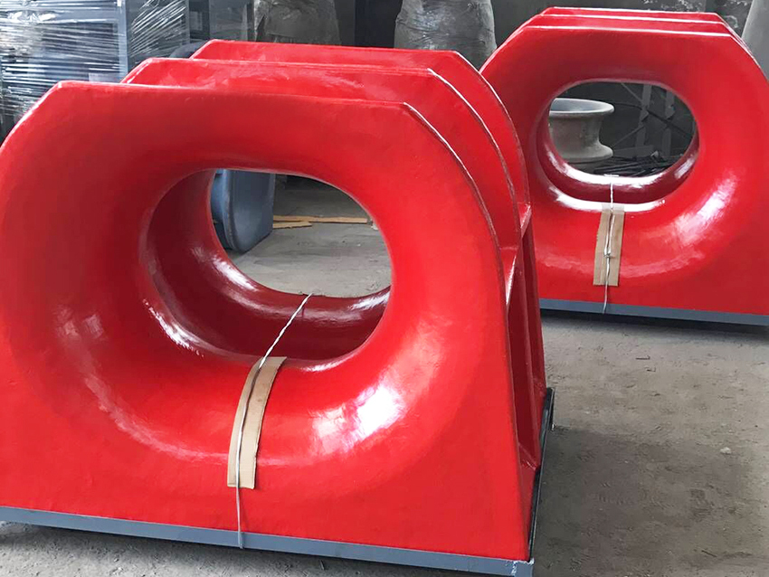
There is no defensible universal winner.
Forging can produce favorable grain flow and reduce certain internal discontinuities. Casting offers flexibility for complex shapes, generous transitions, and integrated structures. Both processes can produce defects, and neither compensates for poor geometry, unsuitable heat treatment, or inadequate inspection.
For continuous mooring service, the better chock is the one with a verified design, controlled production, and an appropriate inspection strategy.
| Evaluation factor | Cast steel chocks | Forged steel chocks |
|---|---|---|
| Manufacturing route | Molten steel solidifies in a mold | Steel is shaped through compressive deformation |
| Design flexibility | Well suited to complex, integrated geometries | Influenced by forging access, tooling, and machining |
| Potential discontinuities | Shrinkage, porosity, inclusions, hot tears | Laps, seams, inclusions, forging cracks |
| Fatigue-sensitive details | Surface quality, internal soundness, section transitions | Grain-flow orientation, surface condition, section transitions |
| Purchasing priority | Casting quality and documented acceptance criteria | Forging quality and documented acceptance criteria |
The comparison must also include the attachment welds and supporting structure. An excellent chock body cannot protect an inadequately designed deck connection.
A port may operate continuously, but its chocks do not necessarily experience a constant, identical loading cycle.
Mooring tension changes with vessel movement, wind, waves, current, tide, passing ships, cargo operations, and winch behavior. Some changes are slow. Others create short-duration tension peaks.
Consequently, operating hours are not a substitute for a fatigue load spectrum.
One vessel visit can produce many stress cycles. Conversely, thousands of small fluctuations may contribute less fatigue damage than a smaller number of severe events.
A meaningful operating description should identify:
- Typical and maximum line tensions.
- Horizontal and vertical lead angles.
- Changes in loading direction.
- Vessel occupancy and berth exposure.
- Unusual overloads or documented incidents.
- Expected corrosion and wear conditions.
These inputs help engineers translate berth activity into local stresses at the chock, its attachment, and its foundation.
This article focuses primarily on shipboard mooring chocks.
Shore-side fairleads and similar fittings may share fatigue mechanisms, but their supporting structures and governing requirements can differ. A specification should identify the installation rather than treating every port fitting as interchangeable.
Fatigue develops through repeated loading. A crack can initiate and grow even when individual loads remain below the component's static failure load.
Material quality matters because discontinuities, rough surfaces, and abrupt geometric changes can increase local stress or provide crack-initiation sites.
Casting enables designers to integrate substantial bodies and smooth transitions into complex chock shapes.
Its challenge is controlling solidification, particularly around thick sections and changing wall thicknesses. Inspection planning should therefore follow the design's critical regions rather than rely on a generic checklist.
Buyers should request:
- A specified steel grade and heat-treatment condition.
- Heat identification and material test records.
- Defined inspection coverage and acceptance criteria.
- Disclosure and control of repair welding.
- Dimensional verification at critical transitions.
A tensile test certificate alone does not demonstrate the fatigue performance of the finished casting.
Forging is not a guarantee of defect-free material.
Its benefits depend on starting-stock quality, deformation, temperature control, grain-flow direction, heat treatment, and final machining. Poor process control can introduce laps or cracks.
If a supplier claims superior fatigue life, ask whether the evidence concerns a polished specimen, a representative component, or the actual installed design. Those are different levels of proof.
A chock transfers changing rope forces into its attachment and supporting structure. Assessing only the body leaves part of that load path unexamined.
Generous transitions can reduce stress concentration. Sharp corners, abrupt thickness changes, and unfavorable loading directions can increase it.
Rope-contact geometry matters too. The contact surface must suit the intended line and minimize damaging abrasion. IMO guidance specifically addresses fitting compatibility, contact diameter relative to rope diameter, and load-bearing surface condition.
A stronger chock is not automatically a better mooring interface if its contact geometry damages the rope.
For welded installations, fatigue assessment should include weld toes, roots, attachment transitions, and the supporting deck or foundation.
Switching from cast steel to forged steel may offer little practical improvement if a weld detail remains the governing fatigue location.
Before approving a material upgrade, ask: which detail currently limits the assessed life, and will this change improve that detail?
Coating breakdown, pitting, and section loss can change the conditions assumed during design. Wear can also alter rope-contact surfaces.
Do not treat laboratory fatigue data as a direct prediction of an exposed marine component's life. The assessment must address the expected environment and maintenance condition.
An engineering estimate connects service loading to the fatigue resistance of the actual structural details.
Start with measured data where available. Otherwise, develop justified operating scenarios covering relevant environmental conditions, vessel behavior, and line arrangements.
Record the assumptions. A precisely calculated answer remains unreliable when its loading assumptions are unrealistic.
Convert line forces into stresses at critical locations.
Depending on complexity, engineers may use analytical calculations, finite element analysis, or both. The model should represent relevant lead angles, contact assumptions, attachment stiffness, and supporting structure.
An S–N curve relates stress range to the number of cycles associated with fatigue failure.
The chosen curve or assessment method must suit the material, structural detail, surface condition, and environment. Polished specimen data should not be assigned directly to an as-cast surface or welded attachment without justification.
For variable loading, a common starting point is Miner's rule:
D=i∑ni/Ni
Here, \(n_i\) is the applied number of cycles in a stress-range group, and \(N_i\) is the corresponding fatigue life from the selected curve.
This is an engineering approximation, not a warranty. Load sequence, uncertainty, and the applicable assessment framework influence how results should be interpreted.
Consider two hypothetical chock installations assessed using the same fatigue curve and loading assumptions.
Suppose an improved transition or attachment reduces the relevant stress range by 20%. For an illustrative S–N relationship with slope \(m=3\), the calculated life ratio is:
Nimproved/Noriginal=(1/0.8)3≈1.95
Under those assumptions, calculated life is approximately doubled.
This is not Taidun test data or a prediction for a particular chock. Different fatigue curves, environments, and governing details can produce different results.
The practical lesson is that reducing a critical stress concentration may be more valuable than changing manufacturing route while leaving the same weak detail untouched.
For brands, wholesalers, and manufacturers, a repeatable specification provides more protection than a general promise of "heavy-duty quality."
Include:
1. Chock type, dimensions, and installation drawing.
2. Intended mooring or towing duty.
3. Required load rating and governing specification.
4. Rope type, diameter, and lead-angle envelope.
5. Material grade and permitted manufacturing routes.
6. Heat-treatment and inspection requirements.
7. Coating system and environmental exposure.
8. Marking, traceability, and documentation requirements.
Distinguish clearly between working-load requirements, test requirements, and any requested fatigue assessment. These are not interchangeable.
The purchase specification should establish inspection methods, coverage, timing, acceptance criteria, and reporting.
Magnetic particle testing can help identify surface and near-surface discontinuities in suitable ferromagnetic materials. Ultrasonic testing can investigate internal discontinuities, subject to geometry and test limitations.
Neither method measures remaining fatigue life directly. Inspection results must be interpreted alongside design and service information.
Evaluate more than the unit price:
- Tooling and minimum order quantity.
- Machining and inspection scope.
- Documentation and traceability.
- Installation compatibility.
- Maintenance accessibility.
- Replacement downtime and supply continuity.
A more expensive manufacturing route is justified when it addresses a demonstrated requirement—not merely because its name sounds stronger.
Establish a documented baseline before commissioning. Record identification marks, installation condition, coating condition, and relevant inspection results.
During service, focus attention on:
- Cracks or suspicious linear indications.
- Distortion and local damage.
- Attachment welds and supporting structure.
- Corrosion, pitting, and coating breakdown.
- Grooves or roughness on rope-contact surfaces.
Set inspection intervals according to the applicable requirements, manufacturer guidance, operating exposure, and inspection history. Do not invent a universal interval for every berth.
After a significant overload or collision, arrange an appropriate technical assessment. Suspected cracking should trigger controlled operational decisions rather than an assumption that the original rating still applies.
For OEM enquiries to Nanjing Taidun Marine Equipment Engineering Co.,Ltd, submit the installation drawing, intended duty, load requirements, rope information, and documentation expectations together.
Request a project-specific review of manufacturing feasibility, inspection scope, and supply requirements. Where fatigue verification is needed, define its technical basis and responsible approval parties before placing the order.
The purchasing objective is not simply "cast" or "forged." It is a traceable fitting whose design, manufacture, installation, and maintenance match the intended service.

No. Forging can offer material advantages, but actual fatigue performance also depends on geometry, defects, heat treatment, surface condition, loading, and attachment details.
No universal figure is reliable. A defensible estimate requires a load spectrum, an appropriate fatigue assessment, environmental assumptions, and inspection information.
No. It demonstrates performance under specified test conditions. It does not reproduce years of variable loading or establish a complete fatigue-life prediction.
Not necessarily. If a weld, stress concentration, or surface discontinuity governs performance, higher material strength alone may not resolve the problem.
Prioritize material traceability, heat treatment, dimensional inspection, specified nondestructive testing, repair records where applicable, and agreed load-test documentation.
After suspected cracking, significant overload, collision damage, substantial corrosion, or changes to the mooring arrangement that may alter loading.
1. International Maritime Organization. "Safe Mooring." Explains the amended SOLAS regulation II-1/3-8, its entry into force on 1 January 2024, and the associated design and maintenance guidance. Applicability must be checked for the vessel concerned. [imo]
2. International Maritime Organization. *MSC.1/Circ.1619 — Guidelines on the Design of Mooring Arrangements and the Selection of Appropriate Mooring Equipment and Fittings for Safe Mooring*, 11 December 2020. Supports the discussion of line–fitting compatibility, contact geometry, abrasion, and supporting structures. [wwwcdn.imo]
3. International Maritime Organization. *MSC.1/Circ.1620 — Guidelines for Inspection and Maintenance of Mooring Equipment Including Lines*, 24 December 2020. Supports documented inspection and maintenance procedures. [wwwcdn.imo]
4. Lloyd's Register. "Anchoring, Mooring and Towing (IACS UR A1, A2 & Rec 10)," 27 June 2018. Summarizes requirements addressing fitting design loads, corrosion and wear allowances, and supporting-structure analysis. [lr]
5. TWI. "Investigation of Fatigue Damage to Welded Joints under Variable Amplitude Loading Spectra." Supports the explanation of S–N data, cumulative damage assessment, and limitations of Miner's rule under variable-amplitude loading. The cited research concerns welded joints, not a direct cast-versus-forged chock comparison. [twi-global]
6. Steel Founders' Society of America. *Purchasing Steel Castings*. Provides a purchasing and supplier-selection reference for steel castings; it does not establish a universal chock fatigue-life figure. [sfsa]
7. Nanjing Taidun Marine Equipment Engineering Co.,Ltd. Corporate website. Used only for company positioning and its stated OEM/ODM service offering—not as independent verification of fatigue performance or project-specific certification. [taidunmarine]
Hot Tags: China, Global, OEM, private label, manufacturers, factory, suppliers, manufacturing company


