

Views: 268 Author: Nanjing Taidun Publish Time: 2026-10-26 Origin: Site
Content Menu
● Hydro-Pneumatic Fender vs Pneumatic Fender: What Changes?
● Why Low Freeboard Ships Need a Contact-Geometry Assessment
>> Fender Stability Is Not the Same as Ship Stability
● How Hydro-Pneumatic Fenders Manage Submerged Contact
>> Water Filling Establishes Part of the Immersion Arrangement
>> Compressed Air Provides the Cushioning Response
>> Ballast Helps Maintain the Intended Orientation
● When a Conventional Pneumatic Fender Is the Better Fit
● A Six-Step Selection Process for OEM Buyers
>> 1. Define the Operating Envelope
>> 2. Map the Permitted Hull-Contact Zone
>> 3. Establish the Design Energy
>> 4. Check Reaction and Hull Pressure
>> 5. Verify Position Across Operating Conditions
>> 6. Define Testing and Acceptance
● An Illustrative Decision Scenario: Surface Protection or Submerged Protection?
● What ISO 17357-1 and PIANC Guidance Actually Establish
● Commissioning and Maintenance: Protect the Intended Configuration
● OEM Procurement with Nanjing Taidun Marine
>> 1. What is the main difference between hydro-pneumatic and pneumatic fenders?
>> 2. Does every low-freeboard ship need a hydro-pneumatic fender?
>> 3. Can a standard pneumatic fender simply be filled with water?
>> 4. Do hydro-pneumatic fenders improve a ship's inherent stability?
>> 5. Is ISO 17357-1 certification enough for a complete installation?
>> 6. What information should an OEM buyer send first?
Nanjing Taidun Marine Equipment Engineering Co., Ltd. is a China-based OEM manufacturer of marine rubber fenders, mooring bollards, and marine anchoring products for overseas brands, wholesalers, and manufacturers. For buyers comparing hydro-pneumatic fender vs pneumatic fender solutions, our starting point is the vessel's actual contact geometry—not simply its freeboard or the fender's diameter.
The central difference is positioning. A conventional pneumatic fender floats at the water surface. A hydro-pneumatic fender uses a combination of water filling, air pressure, and ballast to establish a controlled, typically vertical position for below-waterline contact. That makes hydro-pneumatic systems particularly relevant where low freeboard, deep draft, or unusual hull geometry places the required protection below the surface.
This guide explains how to compare both systems, assess operational stability, and prepare a more useful OEM specification.
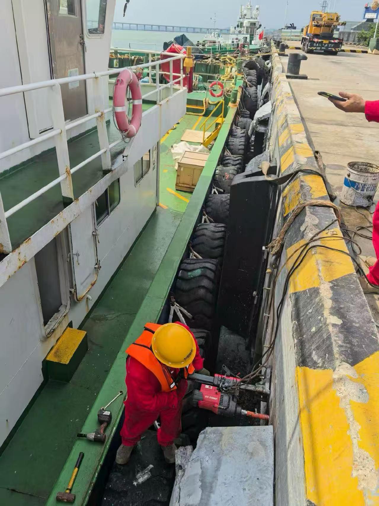
Both systems use compressed air as an important part of their cushioning mechanism. However, their flotation arrangements and intended contact zones differ.
A conventional floating pneumatic fender is an air-filled, reinforced rubber body. It provides separation and absorbs energy during berthing or vessel-to-vessel contact.
A hydro-pneumatic fender is partially water-filled, pressurized with air, and ballasted to maintain its intended orientation. Adjusting the water-to-air ratio and inflation pressure changes its draft and performance. These settings therefore require engineering control rather than informal adjustment on site.
| Selection factor | Conventional pneumatic fender | Hydro-pneumatic fender |
|---|---|---|
| Typical position | Floating at the water surface | Controlled, partially submerged position |
| Internal arrangement | Primarily compressed air | Water and compressed air |
| Orientation control | Flotation and restraint arrangement | Flotation, ballast, and restraint arrangement |
| Main application | General berthing and ship-to-ship operations | Protection where contact occurs below the waterline |
| Key specification issue | Energy, reaction, clearance, and contact geometry | Those requirements plus draft, ballast, and submerged contact position |
| Commissioning focus | Pressure, restraint, and placement | Pressure, water fill, ballast, restraint, and placement |
These differences describe the operating principles, not a universal ranking. Neither type is automatically the safer or more economical choice.
Freeboard describes the vertical distance between the waterline and the relevant deck reference. It does not, by itself, identify where a fender can safely bear against the hull.
Two vessels with similar freeboard may have very different hull curvature, structural reinforcement, appendages, and permitted contact areas.
For fender selection, the important questions are:
- Where can the hull accept contact?
- How does that position change between loading conditions?
- Will the fender remain engaged during relative motion?
- Can the arrangement protect the hull without contacting sensitive equipment?
- Is adequate clearance maintained throughout the operating envelope?
Hydro-pneumatic fenders are specifically used for submarines and other vessels requiring protection below the waterline. However, low freeboard alone does not establish that requirement. The decision should follow the actual interaction between vessel geometry and the proposed fender system.
In this article, "stability management" means maintaining the fender's intended orientation, immersion, and contact position.
It does not mean that a hydro-pneumatic fender improves a ship's inherent intact stability or replaces a naval architect's assessment.
Keeping these concepts separate prevents a specialist fendering solution from being presented as a general cure for vessel motion or stability problems.
A hydro-pneumatic system brings together several interacting design variables.
Partial water filling changes the system's mass and available air volume. Together with the body geometry, ballast, and buoyancy, this helps establish the intended submerged position.
However, a water-fill percentage is not a standalone performance specification. Buyers also need the corresponding pressure, draft, orientation, and verified operating performance.
The air chamber compresses as the fender deforms. Its behavior depends on the starting pressure, air volume, deformation, and complete system configuration.
A catalogue curve for a standard air-filled fender should therefore not be assumed to describe a modified hydro-pneumatic arrangement.
Ballast is used to help the fender stand vertically. The restraint system must also accommodate the intended movement without compromising positioning.
Manufacturer guidance confirms that hydro-pneumatic draft and performance can be tuned through the water-to-air ratio and inflation pressure. Some designs also require stronger construction because of their additional pressure requirements.
*Suggested visual: Insert a labelled cross-section here showing the air chamber, water fill, ballast, waterline, and intended hull-contact zone. Mark it as a conceptual illustration, not an installation drawing.*
A hydro-pneumatic system should solve a demonstrated positioning problem. It should not be specified simply because it sounds more advanced.
Conventional pneumatic fenders are established options for permanent and semi-permanent port applications and offshore ship-to-ship transfers. They can also accommodate a range of tidal conditions, subject to a suitable installation.
Consider a conventional pneumatic arrangement first when:
- The approved hull-contact zone is accessible at the surface.
- The selected size provides sufficient separation.
- Energy absorption and reaction requirements can be met.
- The fender remains correctly positioned during expected movements.
- Restraints, surrounding structures, and handling arrangements are compatible.
From a procurement perspective, unnecessary complexity can create extra inspection and commissioning requirements without delivering a meaningful operational benefit.
A strong enquiry allows an OEM manufacturer to evaluate an application rather than merely quote a diameter.
Provide vessel types, displacement conditions, drafts, freeboards, berth geometry, water-level range, and environmental restrictions.
Include the expected berthing approach and whether the operation involves a fixed berth or another vessel.
Use vessel drawings to identify acceptable bearing areas, hull curvature, projections, and prohibited contact zones.
Check more than one loading condition. A satisfactory arrangement at a single draft may not cover the full operating range.
The familiar kinetic-energy relationship helps explain why approach velocity matters:Ek=1/2mv2
However, this expression alone is not a complete berthing-energy calculation. The engineering assessment must use the applicable design method, operational assumptions, and project factors.
An energy-absorption figure does not establish suitability by itself.
The vessel and supporting structure must also accept the resulting forces. Contact area, hull shape, and the potential involvement of multiple fenders require attention.
For hydro-pneumatic systems, assess the relationship between pressure, filling arrangement, ballast, draft, and restraint geometry.
For conventional pneumatic systems, verify that surface flotation still provides the required protection.
Agree the required drawings, performance evidence, inspection records, commissioning checks, and operating instructions before manufacture.
This requirements-led approach is consistent with PIANC's emphasis on site-specific information and its distinction between catalogue base performance and performance under actual project conditions.
Consider an overseas equipment brand supplying fenders for a berth used by low-freeboard vessels.
This is a hypothetical decision example, not a Taidun customer case study.
Under the first operating condition, the vessel has a suitable structural contact band close to the water surface. A conventional pneumatic fender may provide the required protection if its performance, dimensions, and restraints pass the engineering checks.
Under the second condition, the approved contact band lies below the effective protection zone of the surface-floating fender.
The task then changes. The buyer no longer needs only "more energy absorption"; it needs an appropriately positioned contact surface.
A hydro-pneumatic arrangement becomes worth evaluating because submerged positioning is part of its intended function. The correct next step is to request a configuration-specific assessment—not simply substitute a larger conventional fender.
*Suggested visual: Add a two-panel diagram comparing these conditions. Show the approved hull-contact band and identify why the proposed fender does or does not reach it.*
Standards are valuable only when buyers understand their scope.
ISO 17357-1:2014 specifies materials, performance, dimensions, testing, and inspection for high-pressure floating pneumatic rubber fenders used between ships or between ships and berthing structures. [iso]
That scope should not be interpreted as automatic approval of every customized hydro-pneumatic installation.
For a water-filled, ballasted, or otherwise modified configuration, ask the supplier to identify:
- Which requirements apply directly.
- Which characteristics have been tested.
- Which performance values apply to the proposed configuration.
- What additional engineering verification is required.
- Which documents demonstrate compliance.
PIANC Fender Guidelines 2024, developed by Working Group 211, address the design, manufacture, and testing of fender systems. PIANC specifically warns against merely replacing the older guideline reference in an existing specification without reviewing the changed design approach.
The procurement lesson is straightforward: request evidence that matches the delivered system, not a standards logo detached from its scope.
A suitable design still needs controlled installation and operation.
For hydro-pneumatic systems, the approved configuration should be recorded clearly enough that operators can recognize an unintended change.
A project-specific commissioning checklist should cover:
1. Identification of the delivered unit and approved drawing.
2. Inflation pressure and the specified measurement conditions.
3. Water-fill and ballast configuration.
4. Observed draft and orientation.
5. Restraint installation and available movement.
6. Clearance from hull appendages and nearby structures.
7. Acceptance records and responsibility for future inspections.
Operating documentation should explain inspection intervals, permissible adjustments, isolation procedures, and conditions requiring technical review.
Changes to water fill, ballast, or pressure should not be treated as interchangeable ways to "improve stability." They can alter positioning and performance together. The manufacturer's approved procedure must govern any adjustment.
*Suggested video: Demonstrate an approved commissioning inspection, focusing on pressure verification, orientation checks, and recordkeeping. Avoid presenting a generic filling procedure as suitable for every design.*
For international brands, wholesalers, and manufacturers, a useful OEM enquiry connects commercial requirements with engineering information.
When approaching Nanjing Taidun Marine Equipment Engineering Co., Ltd., provide:
- Vessel and berth drawings.
- Intended contact depth and operating drafts.
- Required energy absorption and maximum reaction.
- Hull-pressure or structural limitations.
- Environmental and handling conditions.
- Required standards and inspection scope.
- Branding, packaging, documentation, and destination requirements.
Use the quotation stage to establish the proposed supply scope, technical responsibilities, acceptance criteria, and evidence required before shipment.
Contact Nanjing Taidun Marine with your vessel drawings and operating conditions to discuss an OEM fender enquiry. Request a documented technical proposal before confirming the final configuration.
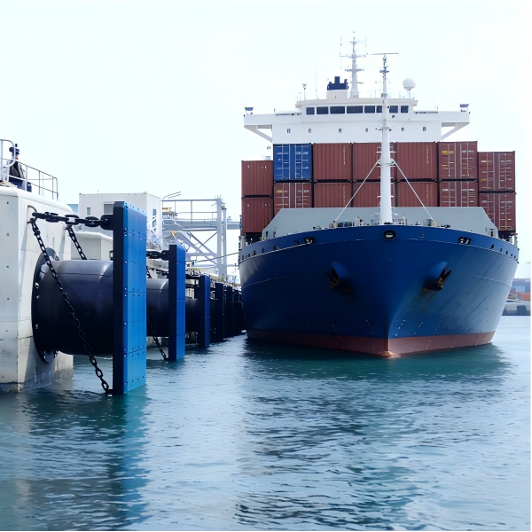
A conventional pneumatic fender floats at the surface. A hydro-pneumatic fender combines partial water filling, compressed air, and ballast to provide controlled positioning for applications including below-waterline contact.
No. The determining issue is whether the proposed system reaches an approved hull-contact zone throughout the operating conditions. Low freeboard is relevant, but it is not a complete selection criterion.
Do not assume so. Hydro-pneumatic systems require a defined filling, pressure, ballast, and positioning arrangement. Specialist designs may also need stronger construction because of additional pressure requirements.
That is not their stated function. Their relevant role is controlled fender positioning and protection at the required contact depth. Vessel stability remains a separate engineering matter.
The standard addresses specified high-pressure floating pneumatic fender characteristics and testing. A complete installation also requires project-specific assessment of geometry, performance, supporting components, and operating conditions.
Start with vessel geometry, operating drafts, intended contact location, berth layout, design energy, force limits, and required inspection documentation. These inputs support a requirements-led selection rather than a size-only quotation.
Hot Tags: China, Global, OEM, private label, manufacturers, factory, suppliers, manufacturing company


