

Views: 342 Author: NANJNG TAIDUN Publish Time: 2026-10-17 Origin: Site
Content Menu
● What "Parallel" and "Angular" Berthing Actually Mean in Fender Design
● The Physics: Why Angle Matters More Than Most Specifications Admit
>> The Angular Factor: Data That Changes Selection
>> The Parallel Motion Exception
● How Fender Type Affects Jetty Lifespan: A Comparative Analysis
>> Conventional Cone and Cell Fenders Under Angular Contact
>> Parallel Motion and Vertical-Panel Systems
>> Pneumatic and Floating Fenders: A Different Trade-off
● PIANC WG211's New Emphasis on Realistic Berthing Angles
>> What This Means for Fender Selection
● Practical Selection Framework: Matching Fender Type to Berthing Reality
>> When Parallel Berthing Dominates (Angle < 2°)
>> When Angular Berthing Is Routine (Angle 5–20°)
>> Critical Specification Checklist
● Conclusion: The Angle Is Not Optional
● Frequently Asked Questions (FAQ)
>> 1. What is the difference between approach angle and berthing angle at contact?
>> 2. How much energy absorption is lost at 20° berthing with conventional fenders?
>> 3. Does PIANC WG211 require angle-corrected fender performance data?
>> 4. Can I retrofit a jetty with fenders optimised for angular berthing?
>> 5. What documentation should I request to verify angular performance?
>> 6. How does UHMW-PE facing wear differ under angular vs. parallel contact?
Introduction: The Angle You Ignore Today Becomes Tomorrow's Repair Bill
Most jetty designs assume vessels arrive perfectly parallel to the berth. In reality, they rarely do. Pilots use angles to control approach speed, currents push hulls off-line, and small vessels routinely land bow-first before pivoting into position. The berthing angle at the moment of fender contact—not the approach angle—determines how much energy your fender system actually absorbs. And the fender type you choose dictates whether that energy is managed gracefully or transferred destructively into your jetty structure.
With over 23 years manufacturing rubber fenders, mooring bollards, fender steel panels, and UHMW-PE pads for ports in more than 80 countries, we have seen how this single design decision separates jetties that last 20 years from those requiring fender replacement within five. This article compares parallel vs. angular berthing performance across fender types, with practical guidance for extending jetty lifespan.
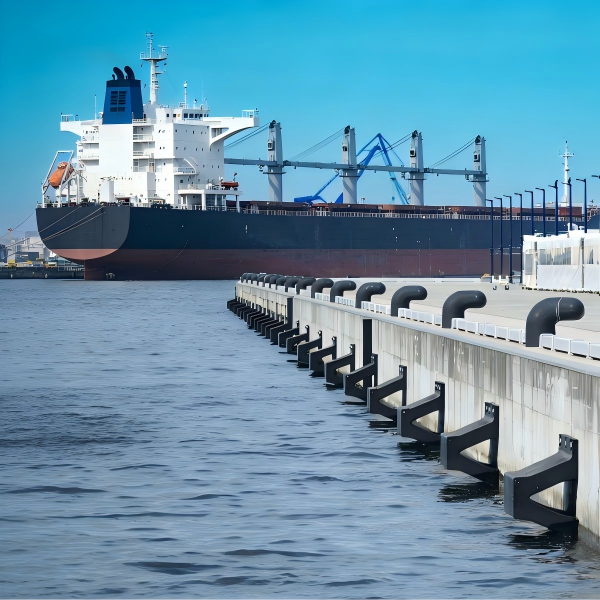
The terminology is often misunderstood. Parallel berthing does not mean the vessel touches the fender at zero degrees. PIANC WG211 defines parallel berthing as a manoeuvre where the vessel is positioned off the berth and approaches with the hull roughly aligned to the quay face . At the moment of first contact, the characteristic berthing angle is typically low—often under 1° for large vessels with tug assistance, based on measured data from European container terminals .
Angular berthing, by contrast, involves a deliberate or incidental angle at contact. PIANC WG211 tabulates characteristic angles ranging from 2° to 3° for well-controlled parallel approaches, up to 8° to 15° for smaller coastal vessels using spring lines and engine thrust . The distinction matters because the angular factor (Cang) in berthing energy calculations directly reduces the effective energy a fender can absorb at angled contact .
When a vessel contacts a fender at an angle, two things happen simultaneously. First, the fender experiences non-uniform compression across its face—one edge compresses more than the other, reducing the effective rubber volume doing work. Second, the reaction force vector is no longer perpendicular to the quay, introducing shear and torsional loads that the fender panel and anchoring system must resist.
Recent experimental research on cone fenders confirms what field engineers have long suspected: increasing compression angle reduces both energy absorption and reaction force . The reduction in energy absorption is the critical concern—the fender does less protective work precisely when the vessel is harder to control.
The reaction force reduction sounds beneficial until you realise the load path changes. A lower perpendicular reaction does not mean lower total force on the structure; it means more of that force is directed into shear and bending rather than axial compression.
Not all fenders degrade equally at angle. Trelleborg's Parallel Motion Fender (PMF) technology demonstrates a fundamentally different behaviour. Comparative testing shows:
| Fender Type | Energy at 0° | Energy at 20° | Efficiency at 20° | Reaction Force |
|---|---|---|---|---|
| PMF SCN1200 | 2,186.6 kNm | 2,186.6 kNm | 100% | 1,955.5 kN |
| Super Cone SCN1200 | 2,182.2 kNm | 1,612.6 kNm | 43% | 3,347.2 kN |
| Cell Fender SCK1450 | 2,153.2 kNm | 1,403.9 kNm | 37% | 3,381.2 kN |
The PMF achieves this through a vertical, non-tilting panel that maintains consistent hull contact regardless of approach angle, combined with back-to-back Super Cone units that extend deflection travel without proportionally increasing stiffness . For jetties where angular contact is unavoidable—RoRo berths, ferry terminals, exposed locations—this performance difference translates directly into reduced structural fatigue and longer service life.
The fender is not an isolated component. It is the first line of load transfer between vessel and jetty. When a fender performs poorly at angle, the consequences propagate into the structure.
These fenders are designed for parallel, face-on compression. When contact occurs at angle:
- Effective rubber volume decreases, reducing energy absorption
- Edge loading concentrates stress on a narrow band of rubber, accelerating wear
- Panel tilting (for tilting-panel designs) can cause uneven load distribution to chains and anchors
- Reaction force increases relative to energy absorbed, raising structural demand
For a jetty designed around a 15–20 year service life, repeated angular contacts accelerate the fatigue cycle. The fender may survive, but the anchoring system, panel connections, and concrete embedment absorb cumulative damage that is difficult to inspect and expensive to repair.
Systems that maintain a vertical panel face through the berthing cycle change this equation. The PMF's free-rotation hinge and closed-box torsion tube allow the panel to accommodate large berthing angles while keeping the rubber units in optimal compression . The result is:
- Consistent energy absorption across the angle range
- Lower peak reaction forces transmitted to the structure
- Reduced shear and torsion on anchors and embedment
- Predictable wear patterns on UHMW-PE facings
For a jetty owner, the lifecycle implication is straightforward: less structural fatigue per berthing event compounds into extended intervals between major maintenance interventions.
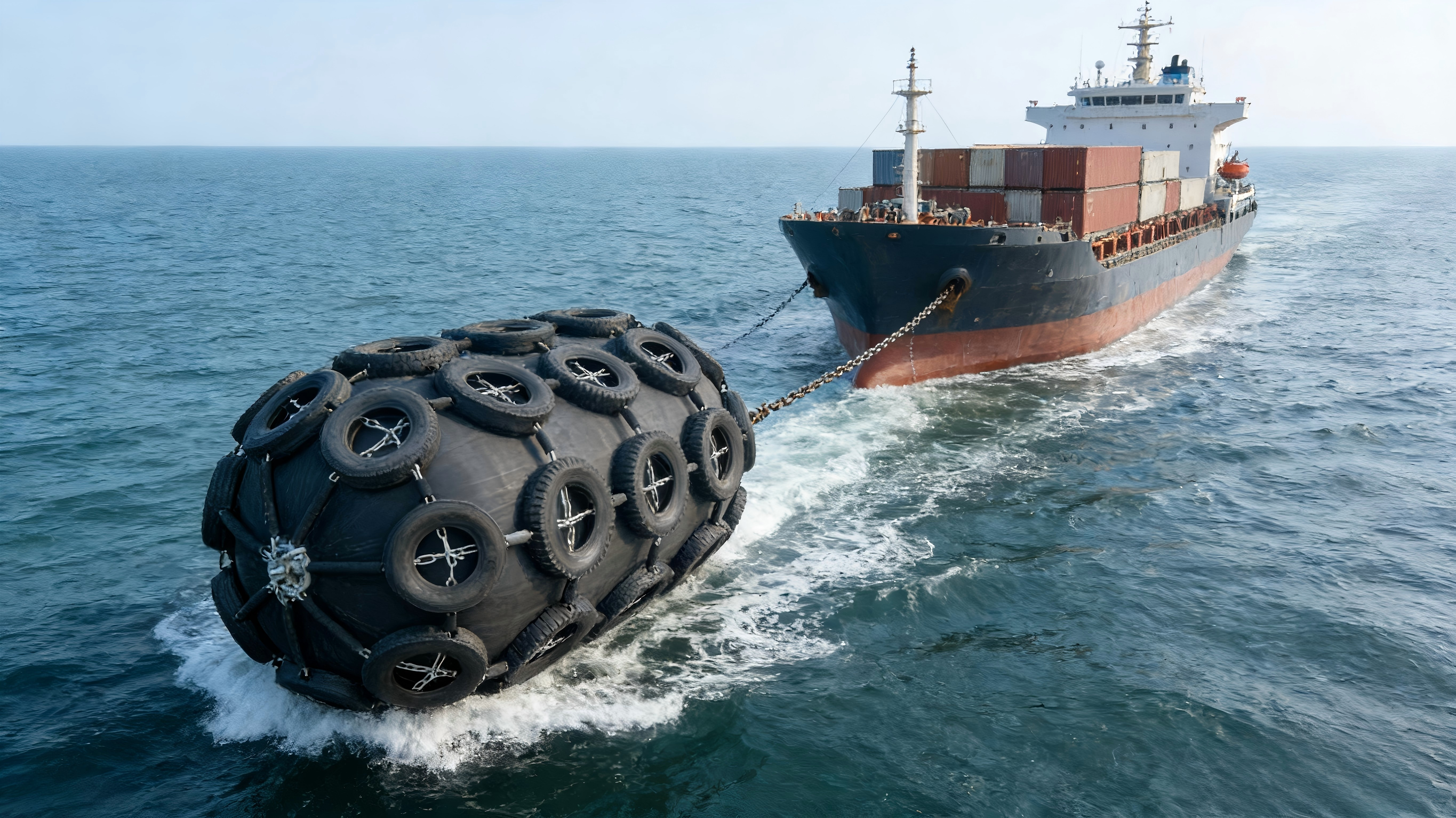
Floating pneumatic fenders handle angular contact through geometry rather than panel mechanics. Their spherical or cylindrical shape distributes contact stresses more evenly at angle, and their buoyancy allows them to reposition relative to the vessel. However, they are not immune to angular performance loss—the effective compression area still changes with contact geometry.
For jetties with moderate to high tidal variation, floating fenders remain a strong choice. But for fixed berths where angular contact is the dominant challenge, panel-based systems with vertical-face geometry offer superior structural protection.
The 2024 PIANC WG211 guidelines represent a significant shift from the prescriptive WG33 approach. One of the most consequential changes is the requirement for site-specific berthing angle data rather than default tables .
Under WG211, designers can no longer assume a generic "parallel berthing" scenario. The guidelines require:
1. Characteristic berthing angle (ac) for energy calculation and fender selection
2. Incidental berthing angle to verify bow or side contact for the smallest design vessel
3. Fender pitch verification to ensure adequate coverage at realistic angles
The implication is clear: the fender must be evaluated at the angle it will actually see, not the angle that produces the most favourable performance curve.
WG211 applies after May 2026 . OEM partners and port operators still specifying under WG33 assumptions face a narrowing window to update their requirements. Fender catalogues must reflect angle-corrected performance data, and testing protocols should verify behaviour under inclined compression—not just vertical laboratory conditions.
Based on our manufacturing experience and the WG211 framework, the following decision guide applies:
| Fender Type | Suitability | Notes |
|---|---|---|
| Super Cone | Excellent | High energy density, proven performance |
| Cell Fender | Good | Cost-effective for moderate energy |
| Cylindrical | Adequate | Lower capacity, frequent replacement |
| PMF | Over-specified | Unnecessary premium for parallel-only berths |
| Fender Type | Suitability | Notes |
|---|---|---|
| PMF / Vertical-Panel | Excellent | Full energy absorption at angle, lowest structural load |
| Pneumatic Floating | Good | Geometry distributes angle contact; tidal flexibility |
| Super Cone (standard panel) | Marginal | Energy loss at angle; higher structural demand |
| Cell Fender | Poor | Significant efficiency loss; accelerated wear |
1. Document the realistic berthing angle from pilot data or WG211 tables
2. Request angle-corrected performance curves from fender suppliers
3. Verify panel and anchor design for the shear loads introduced at angle
4. Specify UHMW-PE facing thickness appropriate for the wear rate at angled contact
5. Require third-party witnessed testing (BV, SGS, ABS, LR) for batch verification
Every jetty will experience angular berthing. The only question is whether the fender system was selected to manage it.
Parallel berthing assumptions produce optimistic energy calculations and undersized reaction force allowances. Angular berthing reality—whether from pilot technique, current, or vessel type—exposes the gap between catalogue performance and installed behaviour.
The choice of fender type is ultimately a lifecycle decision. A system that maintains performance at angle protects not just the vessel, but the concrete, steel, and anchors that constitute your jetty's structural investment. With PIANC WG211 raising the bar for site-specific design, the fenders that perform under realistic angles will define the next generation of durable berths.
At NANJING TAIDUN MARINE EQUIPMENT ENGINEERING CO., LTD, we manufacture fender systems to specification—including panel configurations optimised for angular contact, UHMW-PE facings for extended wear life, and complete documentation packages for WG211 compliance. Our 100,000㎡ facility and CCS, BV, LR, TUV, SGS, and INTERTEK certifications support OEM partners worldwide.
[CTA]
Specifying fenders for a berth with known angular contact?
Contact NANJING TAIDUN for engineering review and OEM manufacturing:
- Email: service@taidunmarine.com
- Website: www.taidunmarine.com
- Services: Custom fender panel design, angle-corrected performance documentation, third-party testing coordination
1. PIANC MarCom WG 211. "Berthing Angle Tables and Angular Factor." [https://www.kscoe.or.kr/!/download/?path=/media/51/board/2025/01/31/7._PIANC_MarCom_WG_211.pdf]
2. KCI. "Proposal of Correction Factors of Berthing Energy Based on Compression Performance Tests with Velocity and Angle as Independent Variables." [https://www.kci.go.kr/kciportal/ci/sereArticleSearch/ciSereArtiView.kci?sereArticleSearchBean.artiId=ART003249415]
3. PIANC Australia. "Navigating PIANC Fender Guidelines 2024 (WG211) for Designers and Asset Owners." [https://pianc.org.au/wp-content/uploads/2025/12/Presentation-Slide-Master-PIANC-Fender-Workshop-30-July-2025-Brisbane.pdf]
4.PIANC Australia. "Insights into PIANC Fender Guidelines 2024 (WG211)." [https://pianc.org.au/wp-content/uploads/2024/08/PIANC-ANZ_Insights-into-PIANC-Fender-Guidelines-2024_July2024.pdf]
Approach angle is the vessel's heading relative to the quay during the manoeuvre. Berthing angle at contact is the angle at the instant the hull touches the fender. PIANC WG211 notes that vessels may approach at a large angle but straighten to a low contact angle just before impact—or, conversely, contact at an angle while still turning . Fender selection should use the contact angle, not the approach angle.
Comparative testing shows Super Cone fenders retain approximately 43% of their 0° energy absorption at 20° contact, while Cell Fenders retain about 37% . Parallel Motion Fenders maintain 100% at the same angle due to their vertical-panel, free-rotation design.
Yes. WG211 requires the angular factor (Cang) to be applied in fender selection calculations, and designers must use site-specific berthing angle data where available . Generic "parallel berthing" assumptions are no longer compliant with the site-specific, risk-based approach of WG211.
Yes, but structural verification is essential. Vertical-panel systems like PMF may impose different anchor loads than the original fenders. For jetties with limited structural capacity, floating pneumatic fenders offer an alternative that transfers angular loads through buoyancy rather than panel mechanics. OEM manufacturers can provide anchor load calculations and panel designs matched to existing embedment.
Request angle-corrected energy absorption and reaction force curves at the specific berthing angles relevant to your site. For critical berths, require third-party witnessed testing (BV, SGS, ABS, LR) that includes inclined compression, not just vertical laboratory tests. Under WG211, "PIANC compliant" claims without angle data are insufficient for verification.
Angular contact concentrates wear on the leading edge of the panel facing, accelerating local material loss. For berths with routine angular contact, specify thicker UHMW-PE facings and inspect edge wear more frequently. Parallel Motion designs use free-rotation hinges to distribute wear more evenly across the facing surface .


