

Views: 265 Author: Nanjing Taidun Publish Time: 2026-09-17 Origin: Site
Content Menu
● What Is a Pneumatic Rubber Fender?
>> How air compression protects vessels
>> Typical pneumatic rubber fender applications
● What Is a Hydro-Pneumatic Fender?
>> Why hydro-pneumatic fenders use water ballast
>> Typical hydro-pneumatic fender applications
● Pneumatic vs Hydro-Pneumatic: Key Differences
● Water Ballasting vs Air Compressing
>> Air compression: the working principle of pneumatic fenders
>> Water ballasting: the control principle of hydro-pneumatic fenders
>> Expert perspective: water is not a substitute for inflation
● How to Select the Right Fender System
>> Choose a pneumatic rubber fender when:
>> Choose a hydro-pneumatic fender when:
>> Five questions to ask before ordering
● OEM Engineering Checklist for Buyers
>> Product and performance requirements
>> Hydro-pneumatic-specific requirements
>> OEM commercial requirements
● Installation and Maintenance Priorities
>> Pneumatic fender installation
>> Hydro-pneumatic fender commissioning
>> Using a standard pneumatic fender for a submerged hull contact point
>> Treating water ratio as a site adjustment without design verification
>> Selecting only by energy absorption
>> Ignoring tidal and operational variation
>> Buying without commissioning documentation
● Why the Fender Decision Matters
● FAQ
>> 1. What is the main difference between pneumatic and hydro-pneumatic fenders?
>> 2. Are hydro-pneumatic fenders only used for submarines?
>> 3. Can a standard pneumatic fender be converted into a hydro-pneumatic fender?
>> 4. Does more air pressure always mean better fender protection?
>> 5. Why is a counterweight needed on a hydro-pneumatic fender?
>> 6. What data should I provide for an OEM hydro-pneumatic fender quotation?
>> 7. Which fender is better for ship-to-ship transfer?
When buyers compare a pneumatic rubber fender vs hydro-pneumatic fender, the real question is not simply "which fender is stronger?" It is whether the berthing point is mainly at the waterline or below the waterline. A standard pneumatic rubber fender relies on compressed air and floats horizontally, while a hydro-pneumatic fender combines water ballasting, compressed air, and counterweight positioning to provide controlled vertical protection for submarines, semi-submersibles, low-freeboard vessels, and other deep-draft applications.
At Nanjing Taidun Marine Equipment Engineering Co., Ltd., we manufacture OEM marine protection and mooring equipment for overseas brands, wholesalers, shipyards, and marine-equipment manufacturers. From our production and project-support experience, the best fender is not selected by diameter alone. It is selected by matching the fender's energy behavior, draft position, installation geometry, maintenance capability, and operational risk to the actual vessel and berth.
This guide explains the engineering difference between air compression in pneumatic rubber fenders and water ballasting in hydro-pneumatic fenders, including when each system should be specified, how to avoid costly selection errors, and what an OEM buyer should confirm before production.
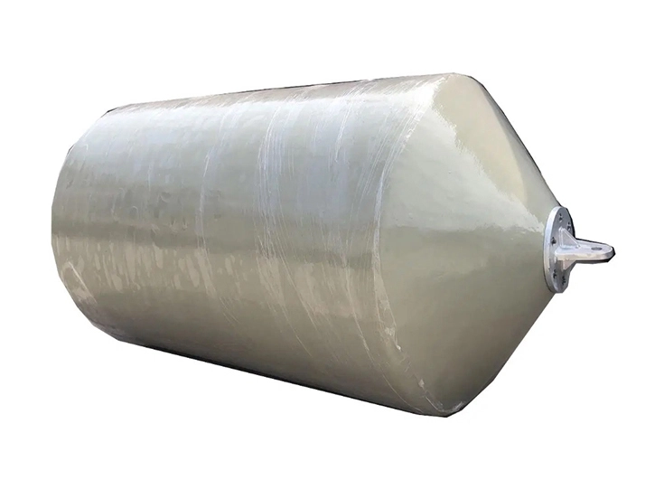
A pneumatic rubber fender is a floating, air-filled marine fender constructed from reinforced rubber layers. It is generally cylindrical, with hemispherical ends, and normally operates in a horizontal orientation between a vessel and a quay, another vessel, or an offshore structure.
The fender absorbs berthing energy through air compression. As the vessel contacts the fender, the fender body deforms and the internal air pressure rises. This progressively cushions the impact and limits the load transmitted to the hull and berth.
Pneumatic fenders are commonly supplied with initial internal pressure ratings such as:
- 50 kPa pneumatic fenders, often called P50
- 80 kPa pneumatic fenders, often called P80
The manufacturer's guaranteed performance data should identify the energy absorption, reaction force, hull pressure, and test pressure at the designated deflection condition. Major suppliers commonly publish both 50 kPa and 80 kPa product ranges, demonstrating that initial pressure is a core engineering variable—not an afterthought. [y-yokohama](https://www.y-yokohama.com/global/product/mb/fenders/floating/)
The core principle is simple: compressed air provides a resilient spring.
During berthing:
1. The vessel contacts the fender.
2. The fender's rubber body compresses.
3. Internal air volume decreases.
4. Air pressure rises.
5. The fender absorbs kinetic energy and develops reaction force.
6. The vessel decelerates before excessive hull-to-berth contact occurs.
For normal ship-to-ship transfer, floating docks, port berths, temporary moorings, and vessel-side protection, this air-based system is highly effective because it is mobile, adaptable, and relatively straightforward to deploy.
A conventional pneumatic fender is usually the right starting point for:
- Ship-to-ship cargo transfer operations
- Tanker berthing and lightering
- Floating terminals
- Port berths with changing tidal conditions
- Naval vessel side protection
- Temporary marine works
- Offshore support-vessel operations
- Locations needing portable or relocatable fendering
Its major strength is floating flexibility. It moves with the water level and remains in a natural horizontal working position when the vessel's contact zone is near the surface.
A hydro-pneumatic fender is a specialized version of a pneumatic fender designed for vertical or near-vertical service where the contact zone is below the waterline. Instead of being filled only with compressed air, it is partially filled with water and then pressurized with air. A counterweight helps keep the fender at its intended vertical draft and operating position.
This configuration is most closely associated with submarine berthing. It is also useful for vessels or structures with a low freeboard, high draft, or submerged contact area. Trelleborg describes hydro-pneumatic fenders as primarily intended for submarines and vessels where contact can occur below the waterline; their performance can be tuned through the water-to-air ratio and inflation pressure. [trelleborg](https://www.trelleborg.com/marine-and-infrastructure/-/media/marine-systems/resources/brochures/downloads/pne-pneumatic-fenders.pdf?rev=bc97b726023244eda1b9ba2ec962158e)
Water is not added simply to make the fender heavier. Water ballast controls the fender's draft, orientation, and submerged protection zone.
A conventional pneumatic fender naturally floats horizontally because its interior is air-filled. That works well when hull contact is near the water surface. It does not work well when the protected hull area is deeply submerged.
A hydro-pneumatic fender solves this problem by using:
- A carefully controlled volume of water
- An air chamber under specified pressure
- A counterweight or ballast arrangement
- A vertical installation method
- Defined target draft and immersion geometry
The result is a fender that can remain positioned where a deep-draft or submerged vessel actually contacts the berth.
Hydro-pneumatic fenders are normally selected for:
- Submarine berths
- Naval bases
- Semi-submersible platforms
- Catamarans with below-waterline contact concerns
- Low-freeboard vessels
- High-draft vessels
- Floating structures with submerged hull interfaces
- Special vertical berthing systems
Industry sources consistently identify hydro-pneumatic fenders as a purpose-built solution for vertical installation and underwater or below-waterline protection. [y-yokohama](https://www.y-yokohama.com/global/product/mb/fenders/download/file/pneumatic_leaflet_2.pdf)
The following comparison helps procurement teams, marine engineers, and brand owners identify the correct system before requesting an OEM quotation.
| Selection Factor | Pneumatic Rubber Fender | Hydro-Pneumatic Fender |
|---|---|---|
| Main energy medium | Compressed air | Compressed air plus water ballast |
| Normal orientation | Horizontal floating | Vertical or controlled vertical |
| Main contact zone | Around the waterline | Below the waterline or across a deep draft range |
| Buoyancy behavior | Naturally floats on the surface | Draft is intentionally controlled |
| Ballasting requirement | Usually no water ballast | Partial water filling is essential |
| Counterweight | Normally not required | Commonly required for vertical stability |
| Typical vessel types | Tankers, cargo ships, STS vessels, general vessels | Submarines, semi-submersibles, low-freeboard vessels |
| Installation complexity | Moderate | Higher; requires controlled filling and positioning |
| Adjustment variables | Internal air pressure, size, quantity, arrangement | Air pressure, water ratio, draft, counterweight, installation geometry |
| Best procurement focus | Mobility, fender size, pressure class, protection net | Ballast design, vertical position, target draft, underwater contact geometry |
The most important distinction is this:
- Pneumatic fenders float because they are air-filled
- Hydro-pneumatic fenders are intentionally ballasted so they protect a selected submerged area
A hydro-pneumatic fender is therefore not merely a pneumatic fender with water inside. It is a different operating system that must be engineered around water ratio, vertical stability, and actual vessel geometry.
In a standard pneumatic rubber fender, the internal air chamber creates the fender's cushioning effect. Larger fenders and higher pressure ratings can generally support higher energy absorption requirements, but they can also produce greater reaction forces.
This is why a buyer should never select a pneumatic fender only by looking for the highest energy absorption figure. The berth structure, hull pressure limit, vessel displacement, berthing velocity, approach angle, and number of fenders all matter.
A correctly selected pneumatic fender balances:
- Energy absorption
- Reaction force
- Hull pressure
- Available contact area
- Tidal movement
- Operational safety margin
Pneumatic fenders are valued because reaction force does not rise as abruptly as with some rigid fender concepts when overloaded, helping reduce damage risk in variable operating conditions. [y-yokohama](https://www.y-yokohama.com/global/product/mb/fenders/floating/)
In a hydro-pneumatic fender, water ballast performs a structural positioning function. The air chamber still absorbs energy, but the water-to-air ratio changes the fender's operating characteristics.
The water fill affects:
- Fender draft
- Vertical balance
- Submerged contact area
- Effective working height
- Reaction-force behavior
- Energy-absorption behavior
- Internal pressure distribution
- Minimum endurable pressure requirements
According to manufacturer guidance, the water volume inside a hydro-pneumatic fender is closely linked to reaction force, guaranteed energy absorption, and minimum endurable pressure.
This means water filling must be treated as an engineering setting, not a field improvisation. An incorrect water ratio can cause the fender to sit at the wrong elevation, rotate improperly, provide inadequate submerged protection, or perform outside the intended design parameters.
One common misunderstanding is that a hydro-pneumatic fender becomes "more protected" simply by adding more water. That is not necessarily true.
Too much water can reduce the air volume available for compression and alter the fender's energy behavior. Too little water can cause insufficient draft control and make the unit float too high. The correct balance depends on the selected fender size, vessel radius, berth geometry, required immersion depth, target reaction force, and the manufacturer's validated performance design.
For OEM projects, we recommend defining the target draft line and water-to-air ratio before production, then providing a clear commissioning procedure with the shipment.
The correct decision begins with the vessel's true contact point—not with the fender catalog.
- The vessel contacts the fender at or near the waterline
- The operation needs floating and horizontal protection
- The fender may be relocated between berths or vessels
- Ship-to-ship operations require a proven, portable solution
- Installation simplicity is a priority
- Tidal change must be accommodated naturally
- The vessel contact zone is substantially below the waterline
- A vertical fender arrangement is required
- The vessel has low freeboard and high draft
- The project involves submarines or specialized naval vessels
- A controlled submerged protection range is essential
- The berth geometry requires the fender to maintain a specific draft position
1. What vessel types will berth at the facility?
Collect displacement, hull geometry, draft range, freeboard, and berthing speed.
2. Where is the actual contact zone?
Identify whether it is above, at, or below the waterline at all operating tide levels.
3. What energy and reaction-force limits apply?
Fender capacity must protect both the vessel and the supporting structure.
4. Will the fender work horizontally or vertically?
Orientation changes the selection fundamentally.
5. Who will maintain and commission the fender?
Hydro-pneumatic systems require more disciplined setup, including controlled filling, pressure verification, and ballast positioning.
As an OEM manufacturer, Nanjing Taidun Marine Equipment Engineering Co., Ltd. works with brands and marine-equipment companies that need more than a generic product. They need consistent quality, technical documentation, flexible configuration, and product identity aligned with their own market.
Before manufacturing, the buyer should confirm the following items.
- Fender type: pneumatic or hydro-pneumatic
- Nominal diameter and length
- Initial internal pressure
- Required energy absorption
- Maximum allowable reaction force
- Target hull pressure
- Working orientation
- Required safety valve configuration
- Rubber compound requirements
- Reinforcement-layer requirements
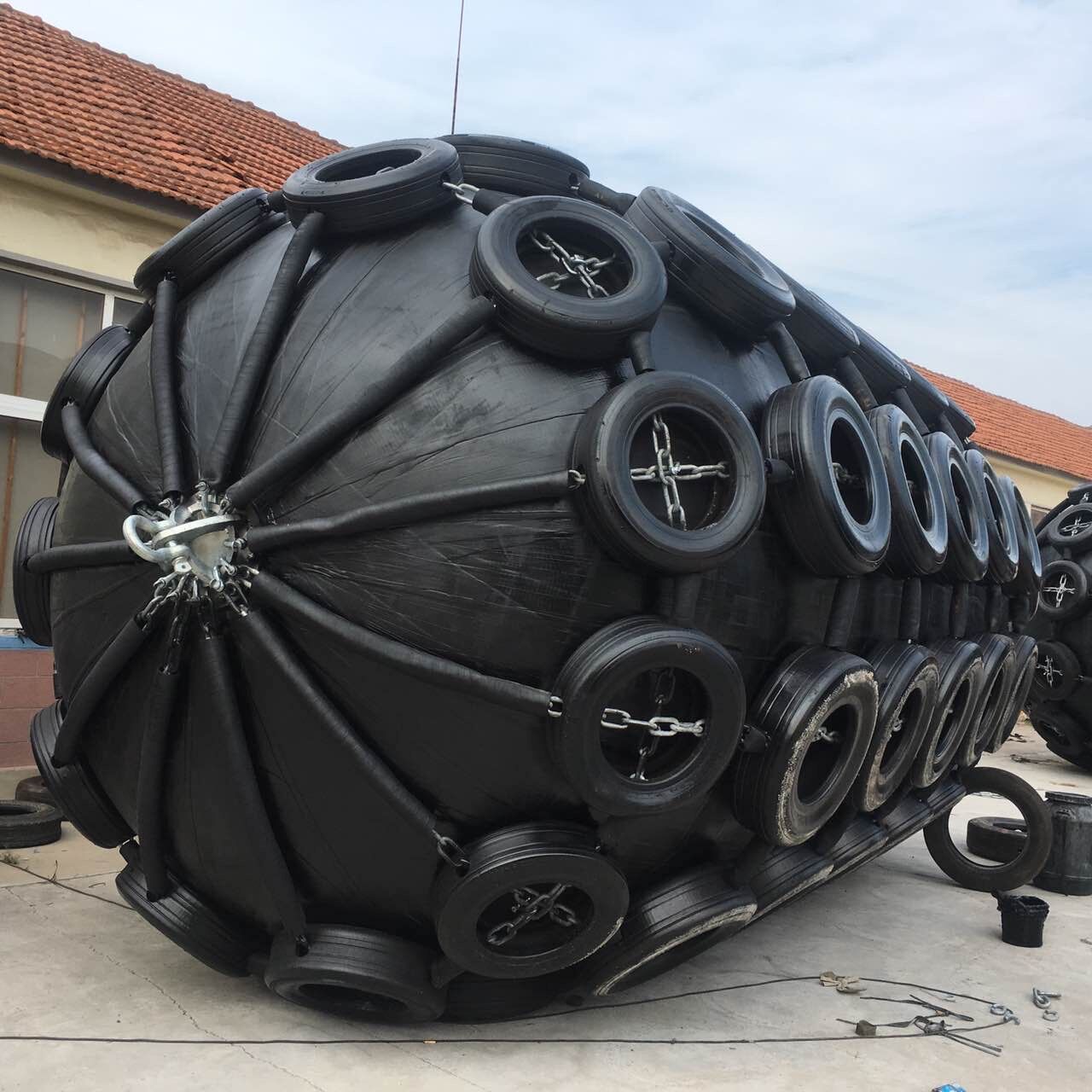
- Protection type: tire-chain net, fiber net, sling type, or no net
- Target installation draft
- Water-to-air ratio
- Required vertical alignment
- Counterweight details
- Mooring and guide method
- Vessel contact elevation
- Commissioning sequence
- Filling and draining connections
- Inspection and maintenance procedure
- Branding on fender body or accessories
- Customized labeling and packaging
- Documentation under the buyer's brand
- Spare-parts package
- Third-party inspection requirements
- Delivery schedule
- Container-loading plan
- After-sales technical support scope
For a private-label program, these details should be frozen before mass production. Changes to pressure level, accessories, net configuration, or ballast design after production begins can affect manufacturing, testing, packaging, and delivery planning.
For standard pneumatic rubber fenders, the installation objective is to allow controlled movement while preventing excessive abrasion, twisting, dragging, and contact with sharp structures.
Routine checks should include:
- Internal pressure verification
- Fender-body inspection for cuts, deep abrasion, and exposed cord
- Flange and valve inspection
- Tire-chain net wear inspection, where fitted
- Shackles, swivel joints, chains, and mooring lines
- Correct floating attitude
- Clearance from propellers, sharp quay edges, and steel projections
Hydro-pneumatic fenders need a documented commissioning process. A typical sequence is:
1. Confirm the model, target draft, water ratio, and counterweight specification.
2. Inspect the fender body, flanges, valves, lifting points, and accessories.
3. Position the fender according to the approved installation drawing.
4. Fill with the specified water volume.
5. Inflate with air to the required pressure.
6. Install or verify the counterweight arrangement.
7. Measure draft, vertical alignment, and contact-zone elevation.
8. Recheck pressure after stabilization.
9. Record final commissioning data for future maintenance.
Do not rely on visual judgement alone. A hydro-pneumatic fender can look acceptable from the surface while still protecting the wrong depth range.
This is the most serious application error. A horizontal floating fender may remain too high to protect a submarine or other deep-draft vessel where contact occurs well below the waterline.
Water ballast changes more than buoyancy. It influences operating draft and performance. The specified ratio should come from the fender design, not from trial-and-error filling.
A high energy rating is not enough. Excessive reaction force can overload berth structures or create unwanted hull loads. Selection must account for both absorbed energy and transmitted force.
The vessel's draft, water level, cargo condition, and berth arrangement can all change the effective contact point. A correct design must consider the full operating envelope, not a single ideal condition.
A specialized fender should be delivered with clear data covering inflation, ballast quantity, draft target, connection points, inspection criteria, and safe handling instructions.
A fender is the final protective interface between expensive marine assets. When the wrong type is selected, the immediate problem may be poor positioning—but the long-term result can include hull damage, berth damage, operational delay, recurring maintenance, insurance exposure, and loss of customer confidence.
The current PIANC Fender Guidelines emphasize the wider objective of fender-system design: protecting vessels and berths while supporting safety, reliability, durability, and optimized total cost of ownership. The 2024 guidance supersedes the former 2002 PIANC approach, reinforcing the importance of system-level design rather than component-only selection. [pianc](https://www.pianc.org/publication/pianc-fender-guidelines-2024/)
For OEM buyers, this means the product specification should be integrated with berth design, vessel profile, operational procedure, and maintenance capacity.
Nanjing Taidun Marine Equipment Engineering Co., Ltd. provides OEM manufacturing support for pneumatic rubber fenders, hydro-pneumatic fenders, mooring bollards, marine anchors, and related marine-equipment solutions.
If your brand, distribution company, shipyard, or marine contractor is evaluating a pneumatic rubber fender vs hydro-pneumatic fender, send us your vessel data, berth drawing, expected operating condition, required standard, branding requirements, and target delivery port. Our team can help you define a practical OEM specification before production starts.
Contact Nanjing Taidun Marine Equipment Engineering Co., Ltd. to discuss your customized fender configuration, OEM packaging, testing requirements, and project-specific technical documentation.
A pneumatic rubber fender is filled primarily with compressed air and usually floats horizontally. A hydro-pneumatic fender is partially filled with water, pressurized with air, and normally configured vertically with counterweight control for below-waterline protection.
No. Submarines are the most common application, but hydro-pneumatic fenders can also be used where vessels or structures have low freeboard, high draft, or a submerged hull contact area requiring vertical protection.
Not safely without an engineered design. A hydro-pneumatic system requires validated water-fill ratio, target draft, counterweight design, vertical installation arrangement, and performance criteria. It should be specified as a hydro-pneumatic fender from the start.
No. Higher pressure can change energy absorption and reaction force. The appropriate pressure depends on vessel size, berth strength, fender size, operating conditions, and allowable hull and structural loads.
The counterweight helps maintain the fender's vertical orientation and designed draft position. Without proper balancing, the fender may float at the wrong elevation or rotate, reducing protection of the intended underwater contact area.
Provide vessel type, draft range, hull radius or contact geometry, berth layout, operating water level, expected berthing energy, allowable reaction force, desired fender dimensions, installation method, target draft line, inspection requirements, and private-label/OEM requirements.
For most ship-to-ship transfer applications, a standard pneumatic rubber fender is the more suitable option because it floats, accommodates water-level changes, and provides reliable cushioning between vessel hulls. Hydro-pneumatic fenders should be considered only when the required contact zone is underwater or the installation requires controlled vertical positioning.
1. Trelleborg Marine and Infrastructure. *Hydro Fenders: Pneumatic Hydro-Pneumatic Fenders.* Explains that hydro-pneumatic fenders are partially water-filled, pressurized with air, and ballasted for submerged applications; it also identifies the relationship between water volume, reaction force, energy absorption, and pressure. [View source](https://www.trelleborg.com/marine-and-infrastructure/-/media/marine-systems/resources/brochures/downloads/hydro-pneumatic-fenders.pdf?rev=173e0b8a874544899b8086b2863c3c53) [trelleborg](https://www.trelleborg.com/marine-and-infrastructure/-/media/marine-systems/resources/brochures/downloads/hydro-pneumatic-fenders.pdf?rev=173e0b8a874544899b8086b2863c3c53)
2. The Yokohama Rubber Co., Ltd. *Floating Fenders.* Product information covering pneumatic fender construction, operational characteristics, testing requirements, and performance data across fender sizes. [View source](https://www.y-yokohama.com/global/product/mb/fenders/floating/) [y-yokohama](https://www.y-yokohama.com/global/product/mb/fenders/floating/)
3. Trelleborg Marine and Infrastructure. *Pneumatic Fenders.* Details standard 50 kPa and 80 kPa pneumatic fender pressure categories and describes hydro-pneumatic fender application for submarines and below-waterline contact conditions. [View source](https://www.trelleborg.com/marine-and-infrastructure/-/media/marine-systems/resources/brochures/downloads/pne-pneumatic-fenders.pdf?rev=bc97b726023244eda1b9ba2ec962158e) [trelleborg](https://www.trelleborg.com/marine-and-infrastructure/-/media/marine-systems/resources/brochures/downloads/pne-pneumatic-fenders.pdf?rev=bc97b726023244eda1b9ba2ec962158e)
4. ShibataFenderTeam. *Hydropneumatic Fenders.* Explains the hydro-pneumatic fender as a special pneumatic-fender version for submarines, partially filled with water and air, with counterweight-supported vertical positioning. [View source](https://www.shibata-fender.team/en/products/floating-fenders/hydropneumatic-fenders.html) [shibata-fender](https://www.shibata-fender.team/en/products/floating-fenders/hydropneumatic-fenders.html)
5. PIANC. *PIANC Fender Guidelines 2024.* States that the Working Group 211 report supersedes the prior 2002 guidance and addresses safe, reliable, durable fender systems with optimized total cost of ownership. [View source](https://www.pianc.org/publication/pianc-fender-guidelines-2024/) [pianc](https://www.pianc.org/publication/pianc-fender-guidelines-2024/)
6. The Yokohama Rubber Co., Ltd. *Pneumatic Fender Leaflet.* Notes that vertical-pneumatic and hydro-pneumatic arrangements address applications where vessel berthing points are below the waterline. [View source](https://www.y-yokohama.com/global/product/mb/fenders/download/file/pneumatic_leaflet_2.pdf) [y-yokohama](https://www.y-yokohama.com/global/product/mb/fenders/download/file/pneumatic_leaflet_2.pdf)
Hot Tags: China, Global, OEM, private label, manufacturers, factory, suppliers, manufacturing company


