

Views: 289 Author: NANJING TAIDUN Publish Time: 2026-11-03 Origin: Site
Content Menu
● What Berthing Energy Actually Measures
>> Why the Old Single-Step Method Fails
● The PIANC WG211 Two-Phase Framework: Characteristic vs. Design Energy
>> Phase 1: Characteristic Berthing Energy (Ek,c)
>> Phase 2: Design Berthing Energy (Ek,d)
● Step-by-Step Berthing Energy Calculation: A Worked Example
>> Step 1: Establish Vessel Characteristics
>> Step 2: Determine Characteristic Berthing Velocity (Vc)
>> Step 3: Calculate Eccentricity Factor (Ce,c)
>> Step 4: Determine Added Mass Factor (Cm,c)
>> Step 5: Calculate Characteristic Berthing Energy
>> Step 6: Apply the Partial Energy Factor
● From Berthing Energy to Fender Selection: The Correction Chain
>> The Fender Capacity Correction Chain
>> For Pneumatic Fenders: ISO 17357-1:2014
● Five Input Errors That Silently Undermine Fender Selection
>> Error 1: Using Deadweight Tonnage Instead of Displacement
>> Error 2: Assuming Zero Berthing Angle
>> Error 3: Ignoring Temperature Effects
>> Error 4: Single-Point Contact Assumption
>> Error 5: Unit Confusion (kJ vs. kNm vs. tf·m)
● Case Example: How Correction Factors Change the Selection
● Practical Recommendations for Port Engineers
>> Documentation to Request from Fender Suppliers
● Conclusion: Precision in Calculation, Confidence in Performance
● Frequently Asked Questions (FAQ)
>> 1. What is the difference between characteristic and design berthing energy?
>> 2. Why can't I use catalogue fender energy directly for selection?
>> 3. What is the added mass factor and why does under-keel clearance matter?
>> 4. How do I determine the correct berthing velocity for my terminal?
>> 5. What is the partial energy factor (γE) and how is it determined?
>> 6. Can berthing energy be absorbed by the wharf structure instead of the fender?
Introduction: The Number That Decides Whether Your Fender Protects the Berth or Fails It
Every fender specification, every purchase order, every warranty claim traces back to one number: berthing energy. Get it right, and the fender system absorbs the impact exactly as designed for the next 15–20 years. Get it wrong—or skip the correction factors—and you either overpay for capacity you don't need or discover your under-specified fender the first time a laden vessel berths in a strong current.
As an OEM manufacturer at NANJING TAIDUN MARINE EQUIPMENT ENGINEERING CO.,LTD, we review berthing energy calculations from port consultants and contractors in over 80 countries. The same gaps appear repeatedly: deadweight tonnage used instead of displacement, velocities lifted from generic tables, and catalogue fender values compared directly against design energy without correction.
This guide provides a practical, engineering-grade walkthrough of berthing energy calculation for marine fender selection, aligned with PIANC WG211. It includes a worked example, a step-by-step procedure you can apply to your next project, and the documentation checklist we recommend to every buyer.

Berthing energy is the kinetic energy a vessel carries at the moment of first contact with the fender system. That energy must be absorbed—by the fender, by the supporting structure, or by a combination of both.
The fundamental design requirement is simple:
Fender Design Capacity (Ef,d) ≥ Design Berthing Energy (Ek,d)
If this inequality holds, the fender performs as intended. If it fails, the consequences range from cosmetic hull damage to structural fatigue and berth downtime.
Many legacy specifications still use a single formula with a blanket safety factor. This approach has two problems.
First, it conflates site conditions with uncertainty. A berth with recorded berthing velocities and a berth with no data at all should not receive the same treatment.
Second, it compares catalogue values directly against site energy. Catalogue fender performance represents laboratory conditions. Real-world performance is lower due to velocity, temperature, and berthing angle effects.
PIANC WG211 addresses both problems through a two-phase framework.
This is the site-specific energy demand without safety factors:
Ek,c = 0.5 × Mc × Vc² × Ce,c × Cm,c
| Symbol | Parameter | Unit | Source |
|---|---|---|---|
| Mc | Characteristic displacement | tonnes | Vessel particulars (operational) |
| Vc | Characteristic berthing velocity | m/s | Site records or PIANC tables |
| Ce,c | Eccentricity factor | dimensionless | Contact geometry |
| Cm,c | Added mass factor | dimensionless | Under-keel clearance ratio |
Ek,d = Ek,c × γE
The partial energy factor γE accounts for navigation condition severity, annual berthing frequency, contact mode (single vs. multiple fenders), and displacement variation over the vessel's service life.
Critical point: γE is not a universal constant. PIANC WG211 requires it to be derived from a berth-specific risk assessment. Using a generic value without justification is not compliant with current guidance.
Let us work through a complete calculation for a realistic design vessel.
| Parameter | Value | Source |
|---|---|---|
| Length between perpendiculars (LBP) | 190 m | Vessel particulars |
| Beam (B) | 32 m | Vessel particulars |
| Draught (T) | 12 m | Governing berthing condition |
| Block coefficient (Cb) | 0.8 | Vessel particulars |
| Water density (ρ) | 1.025 t/m³ | Seawater |
Displacement:
M = LBP × B × T × Cb × ρ
M = 190 × 32 × 12 × 0.8 × 1.025 = 59,800 tonnes
Site-specific berthing records are the preferred source, with the characteristic velocity selected at a 0.02% probability of exceedance. Where records are unavailable, PIANC guideline tables apply.
For this example (moderate navigation conditions, vessel of this size):
Vc = 0.15 m/s
Note: Velocities below 0.10 m/s require site-specific justification or berthing aid systems.
The eccentricity factor accounts for energy dissipated through vessel rotation when berthing is not perfectly parallel.
For a quarter-point berthing contact, with radius of gyration K ≈ 0.25 × LBP:
Ce,c = 0.5
Added mass depends primarily on the under-keel clearance ratio (Uc/D).
- Water depth at berth: 14.4 m
- Vessel draught: 12 m
- Under-keel clearance: 2.4 m
- Uc/D = 2.4 / 12 = 0.2
Reading from PIANC added mass charts for Uc/D = 0.2:
Cm,c = 1.8
Ek,c = 0.5 × 59,800 × 0.15² × 0.5 × 1.8
Ek,c = 0.5 × 59,800 × 0.0225 × 0.5 × 1.8
Ek,c = 605 kNm
For this illustrative example, a placeholder value of γE = 1.6 is applied:
Ek,d = 605 × 1.6 = 968 kNm
Critical caveat: The γE value shown is illustrative only. The actual factor must be derived from the berth-specific risk assessment per PIANC WG211.
Calculating design berthing energy is only half the process. The fender must be selected based on its corrected design capacity (Ef,d)—not its catalogue value.
| Step | Action | Output |
|---|---|---|
| 1 | Start with catalogue energy | Ecatalogue |
| 2 | Apply velocity correction | Evelocity |
| 3 | Apply temperature correction | Etemperature |
| 4 | Apply berthing angle correction | Eangle |
| 5 | Apply multiple fender contact factor | Emultiple |
| 6 | Apply partial resistance factors | Ef,d |
The critical error: comparing catalogue fender performance directly against design berthing energy. Catalogue values represent laboratory conditions—not site conditions.
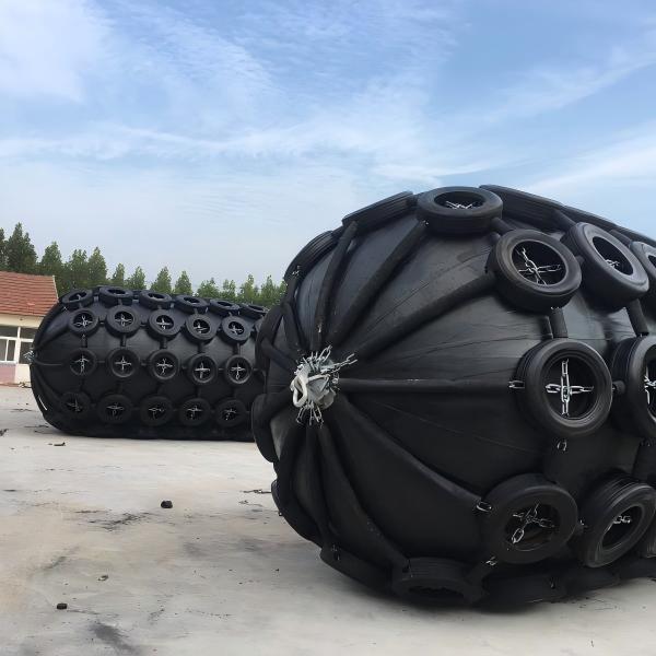
For pneumatic rubber fenders, ISO 17357-1:2014 specifies performance against 50 kPa and 80 kPa initial internal pressure classes. A guaranteed energy absorption (GEA) value quoted without its pressure class is incomplete and unusable for specification purposes.
Over years of reviewing specifications, we have identified five recurring errors that pass unnoticed until a fender underperforms.
DWT is a cargo capacity figure. It is not the vessel mass used in berthing energy. PIANC requires operational displacement for the governing berthing condition. Converting DWT using a fixed ratio introduces error that compounds through the calculation.
A fender that performs adequately at 0° may lose 50% or more of its energy absorption capacity at 20° approach angles. Angular correction is not optional.
Rubber stiffens in cold conditions (higher reaction force) and softens in heat (lower energy absorption). A fender specified for 20°C may not perform as rated at −10°C or 40°C.
PIANC WG211 addresses multiple fender contacts explicitly. Where a vessel contacts more than one fender simultaneously, the load distribution changes. Assuming single-point contact can under-specify individual units.
kJ and kNm are dimensionally equivalent (1 kJ = 1 kNm). Convert only when documents use tonne-force meters (tf·m). Mixing units across a specification package is a common source of order-of-magnitude errors.
Consider a terminal where catalogue fender performance appears sufficient:
| Parameter | Catalogue Value | Site-Corrected Value |
|---|---|---|
| Energy absorption | 1,000 kNm | 850 kNm |
| Correction: velocity | — | × 0.95 |
| Correction: temperature | — | × 0.92 |
| Correction: angle (10°) | — | × 0.97 |
| Corrected capacity | — | 796 kNm |
If design berthing energy is 800 kNm, the fender that appeared adequate is actually under-specified by 4 kNm—a margin that disappears entirely under less favorable conditions.
1. Displacement: Use operational displacement, not DWT
2. Velocity: Obtain from site records or PIANC tables; document the source
3. Eccentricity: Define the impact point; use the appropriate Ce value
4. Added mass: Calculate Uc/D; read from PIANC charts
5. Partial factor: Derive from berth-specific risk assessment
6. Fender correction: Apply all correction factors to catalogue values
7. Pressure class: For pneumatic fenders, specify 50 kPa or 80 kPa
- Catalogue performance curves with test conditions stated
- Correction factor documentation for velocity, temperature, and angle
- Batch-specific compression test reports
- Material certificates for rubber and steel components
- Third-party inspection reports (BV, SGS, ABS, LR, DNV)
Berthing energy calculation is not an academic exercise. It is the engineering foundation on which fender system reliability, port safety, and capital efficiency depend.
The PIANC WG211 methodology—with its characteristic/design energy framework and explicit correction factors—provides the rigor that modern port infrastructure demands. Skipping steps, using ambiguous inputs, or comparing uncorrected values introduces risk that may not manifest for years.
At NANJING TAIDUN MARINE EQUIPMENT ENGINEERING CO.,LTD, we support OEM partners with fender systems manufactured to specification, documented to international standards, and tested to verify performance. Our engineering team can assist with berthing energy review and fender selection verification.
[CTA]
Need fender systems manufactured to your berthing energy specification?
Contact NANJING TAIDUN:
- Email: service@taidunmarine.com
- Website: www.taidunmarine.com
- Services: OEM manufacturing, custom rubber compounding, third-party testing coordination, documentation packages
1. Floating-Fender. "Berthing Energy Calculation: Which Formula Applies Now, and What the Result Must Match." [https://www.floating-fender.com/berthing-energy-calculation/]
2. PIANC MarCom WG 211. "PIANC Fender Guidelines 2024." [https://www.kscoe.or.kr/!/download/?path=/media/51/board/2025/01/31/7._PIANC_MarCom_WG_211.pdf]
3. Japan International Cooperation Agency (JICA). "Berthing Energy Calculation – Port Facility Design." [https://openjicareport.jica.go.jp/pdf/10611598.pdf]
4. PIANC Australia. "Insights into PIANC Fender Guidelines 2024 (WG211)." [https://pianc.org.au/wp-content/uploads/2024/08/PIANC-ANZ_Insights-into-PIANC-Fender-Guidelines-2024_July2024.pdf]
5. Port and Airport Research Institute (Japan). "Fender Design Test Guideline." [http://www.cdit.or.jp/en/FenderDesignTestGuideline.pdf]
6. Nanjing Taidun Marine Equipment Engineering Co.,Ltd. Official website. [https://www.taidunmarine.com/]
Characteristic berthing energy (Ek,c) is the site-specific energy demand calculated from vessel displacement, velocity, eccentricity, and added mass—without safety factors. Design berthing energy (Ek,d) applies a partial energy factor (γE) to account for navigation conditions, berthing frequency, and consequence class. PIANC WG211 requires both values to be calculated separately.
Catalogue fender energy represents base performance under standard laboratory conditions. Real-world performance is lower due to velocity effects, temperature extremes, and berthing angles. PIANC requires applying correction factors to convert catalogue values to site-specific design capacity (Ef,d) before comparison with design berthing energy.
The added mass factor (Cm) accounts for the mass of water that moves with the vessel during berthing. It depends primarily on the under-keel clearance ratio (Uc/D). Shallow water (low Uc/D) increases added mass significantly—a vessel in shallow water has higher effective mass and therefore higher berthing energy. PIANC provides charts for reading Cm based on Uc/D.
Site-specific berthing records are the preferred source, with the characteristic velocity selected at a 0.02% probability of exceedance. When records are unavailable, PIANC guideline tables provide conservative velocities based on vessel size and navigation condition. Velocities below 0.10 m/s require site-specific justification or berthing aid systems.
The partial energy factor converts characteristic energy to design energy, accounting for uncertainties in navigation condition, berthing frequency, contact mode, and displacement variation. Unlike a fixed safety factor, γE is berth-specific and must be derived from a risk assessment per PIANC WG211. Using a generic value without site-specific justification is not compliant with current guidelines.
Yes. Research on flexible high-pile wharf structures shows that elastic deformation of the pile system can absorb a portion of berthing energy under certain conditions. However, this requires coupled structure-fender analysis and is not captured by standard component-level fender selection. For rigid quay walls, this contribution is negligible.


