

Views: 278 Author: Nanjing Taidun Publish Time: 2026-10-30 Origin: Site
Content Menu
● Fender System Components Explained: Start With the Complete Assembly
● How Fender System Components Transfer Berthing Loads
● 1. Rubber Fender Elements: The Energy-Absorbing Core
● 2. Steel Frontal Panels: Distributing Loads Across the Contact Surface
● 3. UHMW-PE Facing Pads: Managing Friction and Wear
>> Details That Deserve More Attention
● 4. Chains, Shackles, and Brackets: Controlling System Movement
● 5. Anchors and Bolts: Connecting the Fender to the Berth
● Fixed, Pneumatic, and Foam Fender Systems: What Changes?
● A Practical OEM Procurement Checklist for Marine Fender Systems
>> Step 1: Establish the Design Basis
>> Step 2: Define Supply Boundaries
>> Step 3: Review Component Interfaces
>> Step 4: Agree on Inspection and Testing
>> Step 5: Control OEM Documentation
>> Step 6: Plan Replacement Support
● Illustrative Replacement Scenario: Why Matching Size Is Not Enough
● Inspection and Maintenance: Follow the Load Path
● Work With Taidun on Your OEM Fender Enquiry
>> What are the main components of a marine fender system?
>> What is the difference between a rubber fender and a complete fender system?
>> Do all rubber fenders need steel frontal panels?
>> Can existing chains and anchors be reused?
>> Which documents should an OEM buyer request?
>> Does PIANC guidance replace project-specific engineering?
Nanjing Taidun Marine Equipment Engineering Co., Ltd. is a China-based OEM manufacturer of marine rubber fenders, mooring bollards, and anchoring equipment for overseas brands, wholesalers, and manufacturers. In this guide, Fender System Components Explained, we examine how individual parts work together—and what buyers should verify before approving a complete marine fender system.
Our perspective is straightforward: buying a rubber fender is not the same as specifying a berth protection system. Performance depends on the relationship between the energy absorber, contact surface, connections, and supporting structure.
For procurement teams, understanding those relationships makes technical discussions clearer, quotation comparisons more meaningful, and replacement planning more reliable.

A marine fender system manages contact between a vessel and a berth or another vessel. Its configuration depends on vessel characteristics, operating conditions, and structural constraints.
A typical panel-equipped fixed rubber fender system includes:
- A rubber energy-absorbing element.
- A steel frontal panel.
- Low-friction facing pads.
- Support and restraint chains.
- Shackles, brackets, and tensioning accessories.
- Anchors, bolts, and structural connections.
Not every arrangement uses every component. An arch fender may contact the vessel directly, while pneumatic and foam-filled systems use different supporting and securing arrangements.
The essential purchasing question is therefore not "Which parts are included?" but "How does this assembly manage the specified loads?"
Understanding the load path helps buyers identify missing engineering information.
In a typical panel-equipped system, vessel contact applies force to the facing pads and frontal panel. The panel distributes that load to the rubber element, which deforms and absorbs energy. Connections transfer the resulting forces into the berth structure.
Friction and angled contact introduce additional actions. These can affect panel movement, chains, brackets, anchors, and the rubber element itself.
Three performance terms deserve particular attention:
| Term | Meaning | Procurement significance |
|---|---|---|
| Energy absorption | Energy managed during fender deformation | Must satisfy the project's design requirement |
| Reaction force | Force generated as the fender compresses | Must remain compatible with vessel and berth limits |
| Hull pressure | Contact load divided by effective contact area | Requires assessment of actual contact conditions |
A large panel does not automatically guarantee acceptable hull pressure. Partial contact, hull geometry, and panel orientation can reduce the effective contact area.
Rubber fender elements deform under compression to manage berthing energy. Common configurations include cone, cell, arch, cylindrical, and other molded or extruded profiles.
Selection should consider more than nominal dimensions or a product name.
Request the following information:
- Required and offered energy absorption.
- Associated reaction force.
- Rated deflection.
- Reference test conditions.
- Applicable temperature, velocity, and angular effects.
- Manufacturing tolerances and acceptance criteria.
Two similarly sized rubber fenders can have different performance characteristics. Compound formulation, geometry, production control, and testing conditions all matter.
From an OEM purchasing perspective, I would treat the performance curve and its stated conditions as essential documents—not optional catalogue attachments.
A suitable specification connects the rubber unit's performance to the complete system design.
The frontal panel connects vessel contact with the rubber energy absorber.
Its functions include distributing reaction loads, supporting facing pads, and providing attachment points for other system components.
Panel design should account for:
- Full-face and partial vessel contact.
- Bending, shear, and local structural effects.
- Connections to rubber units and chains.
- Vessel beltings or other concentrated contact features.
- Corrosion protection and inspection access.
- Handling and lifting arrangements.
A panel is not simply a steel plate selected by thickness. Internal stiffeners, connection details, weld quality, and geometry determine how the assembly behaves.
Sealed box panels also require appropriate fabrication and integrity checks.
For replacement projects, confirm both external dimensions and connection coordinates. Matching the visible outline does not establish structural or mechanical interchangeability.
Ultra-high-molecular-weight polyethylene, usually abbreviated to UHMW-PE, commonly forms the contact surface on steel fender panels.
These pads provide a low-friction, wear-resistant interface between the vessel and the panel.
However, facing pads do not replace the main energy absorber.
When reviewing UHMW-PE fender facing pads, check:
- Material specification and declared properties.
- Pad thickness and fastening arrangement.
- Recessed fasteners and remaining wear allowance.
- Edge geometry and potential snagging points.
- Provision for movement and dimensional changes.
- Accessibility for individual pad replacement.
Colour alone does not demonstrate material quality.
Likewise, a published friction coefficient should not be treated as a universal operating value. Surface condition and the actual contact interface influence friction.
Specify the material and design assumptions rather than relying on appearance.
Chains can support heavy panels and restrict movement that would otherwise overload rubber elements or connections.
Different chain arrangements perform different functions.
| Chain arrangement | Typical purpose | Important review point |
|---|---|---|
| Weight-support chain | Supports panel dead weight | Connection geometry and installed setting |
| Shear-restraint chain | Limits lateral displacement | Compatibility with expected panel movement |
| Tension-restraint chain | Restricts excessive outward movement | Load capacity and engagement position |
| Retention arrangement | Helps prevent loss of components | Project-specific function and load case |
Shackles, brackets, tensioners, and chain anchors belong to the same engineered assembly.
Do not assume that selecting a stronger chain automatically improves the system. Incorrect geometry or adjustment can introduce unintended loads.
Chain length and setting should follow approved drawings. Field adjustment without engineering review can change how the panel and rubber unit move together.
Fender fixing anchors connect the system to the supporting structure. They are different from vessel anchoring equipment, despite sharing the word "anchor."
Depending on the project, connections may use cast-in anchors, qualified post-installed anchors, or other engineered details.
Selection depends on:
- Applied tension, shear, and combined actions.
- Concrete condition and strength.
- Edge distances and anchor spacing.
- Embedment and reinforcement arrangement.
- Installation environment and access.
- Corrosion exposure.
A larger bolt diameter alone does not establish a safe connection.
For refurbishment work, existing concrete and anchor conditions require particular attention. Reusing old fixing positions should depend on verified structural suitability, not installation convenience.
Final anchor design and installation procedures should be approved by the responsible project engineer.
"Marine fender system components" covers several distinct configurations.
| System | Main energy-absorbing mechanism | Components requiring particular attention |
|---|---|---|
| Fixed rubber fender | Rubber deformation | Rubber unit, panel where fitted, restraints, fixings |
| Pneumatic fender | Compression of enclosed air | Fender body, valves, securing arrangement, protective net where fitted |
| Foam-filled fender | Compression of foam core | Core, reinforced outer skin, end connections, securing arrangement |
A component checklist for a cone fender system should not be copied directly into a pneumatic fender enquiry.
Start with the intended application, then define the appropriate assembly and inspection requirements.
For overseas brands and wholesalers, the greatest purchasing risk is often an incomplete technical handover rather than a missing physical component.
Use this six-step process before production approval.
Provide the vessel range, berth layout, operating water levels, contact geometry, environmental conditions, and approved berthing criteria.
Identify who is responsible for application engineering.
State whether the quotation includes rubber units only or complete assemblies.
List panels, pads, chains, fixings, drawings, testing, packaging, and installation documentation separately.
Check hole patterns, connection locations, clearances, panel orientation, and assembly references.
For replacement work, use verified survey measurements rather than photographs alone.
Define required material records, performance testing, dimensional checks, fabrication inspections, coating checks, and acceptance criteria.
Avoid vague instructions such as "standard quality."
Agree on branding, product identification, drawing revisions, packaging marks, and document ownership.
Ensure the delivered parts can be matched to the approved bill of materials.
Identify wear components and critical spare parts before shipment.
A traceable component schedule makes future maintenance and repeat orders easier.
Consider a terminal replacing a damaged panel-equipped fender.
The proposed rubber unit has the same nominal size, and the new panel fits the available berth space. At first glance, the replacement appears straightforward.
However, the new panel has different chain bracket positions and a different weight.
Those changes can alter chain geometry, supported loads, and movement during compression. Existing anchors may also require reassessment.
The practical lesson is to compare the entire assembly:
1. Rubber performance and dimensions.
2. Panel geometry and mass.
3. Chain connections and settings.
4. Fixing positions and structural capacity.
5. Vessel contact conditions.
This is an illustrative engineering scenario, not a claimed Taidun project. Its purpose is to show why apparent dimensional compatibility does not prove system compatibility.
A useful inspection plan follows the same sequence as the loads.
Start at the vessel contact surface, then examine the panel, rubber element, restraints, and structural connections.
Look for:
- Worn pads or exposed fasteners.
- Panel deformation or damaged coatings.
- Rubber cuts, cracks, or unusual deformation.
- Corroded, distorted, or damaged chain components.
- Loose or missing fasteners.
- Concrete cracking or deterioration around fixings.
Inspection intervals should reflect operating exposure, manufacturer instructions, and site risk. Additional checks may be needed after abnormal impacts.
Photograph findings consistently and record component identification. Escalate defects that could affect load capacity to a qualified engineer.
Do not assume that replacing the most visibly damaged part resolves the underlying cause.
Nanjing Taidun Marine Equipment Engineering Co., Ltd. serves overseas brands, wholesalers, and manufacturers seeking OEM marine equipment.
For your next enquiry, send the available drawings, component schedule, quantities, required performance, applicable specification, and delivery destination.
Clearly identify whether you need replacement parts, rubber units, or complete fender assemblies.
Request an itemized proposal showing technical assumptions, supply boundaries, required testing, and documentation. This creates a stronger basis for comparing offers and agreeing on production requirements.
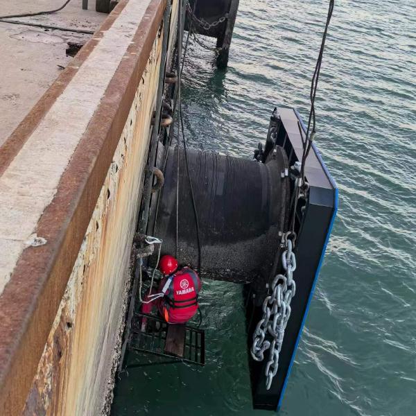
A typical panel-equipped fixed system includes a rubber element, steel panel, UHMW-PE pads, chains, connecting accessories, and structural fixings. Other fender types use different arrangements.
The rubber fender is the energy-absorbing element. The complete system includes the components needed to manage vessel contact, movement, and load transfer into the supporting structure.
No. Some configurations contact the vessel directly. Panel requirements depend on the application, hull-pressure limits, vessel geometry, and selected fender arrangement.
Possibly, but only after their condition, dimensions, capacity, and compatibility with the proposed assembly have been verified. Visual similarity is insufficient.
Request approved drawings, a bill of materials, performance information, agreed inspection records, installation instructions, and component identification. Additional documentation depends on the project specification.
No. PIANC provides technical guidance. The responsible engineer must establish the project requirements and confirm that the selected system suits the vessel, berth, and operating conditions.
1. PIANC, Report No. 211, March 2024 — Guidelines for the Design, Manufacturing and Testing of Fender Systems 2024. The linked publication record and contents identify the report's scope, including chains and fixing-anchor design. [izw.baw]
2. Trelleborg Marine and Infrastructure — PIANC Fender Guidelines 2024 overview. Used for the whole-system approach, component integration, chain functions, and anchorage considerations. This is a manufacturer's explanatory publication, not the full PIANC report. [trelleborg]
3. Trelleborg Marine and Infrastructure — Fender Panels. Used for panel functions, hull-pressure considerations, structural details, connections, corrosion protection, and maintainability. [trelleborg]
4. Trelleborg Marine and Infrastructure — Handling, Storage, Installation and Maintenance of Fender Systems. Used for assembly terminology, component identification, chain arrangements, and installation relationships. [trelleborg]
5. Trelleborg Marine and Infrastructure — Fender Application Design Manual. Used for facing materials, friction considerations, chains, and related component-selection principles. [trelleborg]
6. Google Search Central — Creating Helpful, Reliable, People-First Content. Used as the editorial basis for transparent sourcing, useful original explanation, and avoiding unsupported experience or authority claims. E-E-A-T should not be presented as a certification or ranking guarantee. [developers.google]
7. Company positioning — Supplied by Nanjing Taidun Marine Equipment Engineering Co., Ltd. in the project brief: China-based OEM manufacturing of marine rubber fenders, bollards, and anchoring equipment for overseas brands, wholesalers, and manufacturers. No independent ranking, certification, or performance claim is implied.
Hot Tags: China, Global, OEM, private label, manufacturers, factory, suppliers, manufacturing company


