


Views: 326 Author: NANJING TAIDUN Publish Time: 2026-09-30 Origin: Site
Content Menu
● Introduction: The Invisible Force Protecting Global Maritime Trade
● What Is a Floating Pneumatic Rubber Fender?
>> Key Terminology Clarification
● Construction: The Anatomy of a Pneumatic Rubber Fender
>> Multi-Layer Reinforcement System
>> Standard Specifications (ISO 17357)
● Working Principle: How Floating Pneumatic Fenders Absorb Energy
>> The Physics of Air Compression
>> Performance Advantages Over Alternative Fender Types
● Application Scenarios: Where Floating Pneumatic Fenders Excel
>> Ship-to-Ship (STS) Transfer Operations
>> Ship-to-Dock (STD) Berthing
>> Offshore Platform and Submarine Applications
● CTN vs. Sling Type: Choosing the Right Configuration
>> Chain-Tire-Net (CTN) Configuration
● Expert Insights: Selection Criteria Beyond Size
>> The Energy Absorption Calculation
● Maintenance and Inspection: Extending Service Life
>> Routine Inspection Protocol
>> Common Failure Modes and Prevention
● Market Outlook: The Growing Demand for Marine Fender Solutions
>> 1. What is the difference between pneumatic and hydro-pneumatic fenders?
>> 2. How long do floating pneumatic rubber fenders last?
>> 3. Can pneumatic fenders be used in cold climates?
>> 4. What is the largest pneumatic fender available?
>> 5. What is the typical lead time for pneumatic fender orders?
● Conclusion: Selecting the Right Partner for Your Fender Requirements
Every day, massive vessels—some exceeding 450 meters in length and displacing over 600,000 tonnes—navigate into ports, terminals, and offshore facilities worldwide . The forces generated during berthing are immense. A single misjudged approach can cause hull damage, structural failures, and operational delays costing millions.
Floating pneumatic rubber fenders are the unsung heroes of these operations. These air-filled marine fender systems absorb kinetic energy during ship-to-ship (STS) transfers, ship-to-dock berthing, and offshore loading operations. Their unique design combines low reaction force with high energy absorption capacity, making them indispensable for modern maritime infrastructure .
This guide provides a comprehensive technical breakdown of how floating pneumatic rubber fenders work, their construction, operational principles, and selection criteria. Whether you are a port engineer, ship operator, or procurement specialist sourcing marine fender solutions, this article delivers the technical depth needed to make informed decisions.
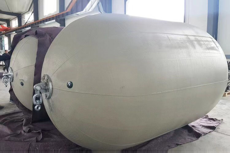
A floating pneumatic rubber fender is a cylindrical, air-filled marine fender constructed from reinforced rubber layers that contain compressed air. Unlike solid rubber fenders or foam-filled alternatives, pneumatic fenders rely on the compressibility of air to absorb impact energy while maintaining relatively low reaction forces on vessel hulls .
The term "floating" refers to the fender's ability to ride on the water surface, automatically adjusting to tidal variations and vessel movements. This self-adjusting capability eliminates the need for complex mechanical systems to accommodate changing water levels .
The industry uses several interchangeable terms:
- Pneumatic fender — The generic technical term
- Pneumatic rubber fender — Emphasizes the rubber construction
- Floating pneumatic fender — Highlights the buoyant configuration
- Yokohama fender — A brand-specific reference originating from Yokohama Rubber Company's 1958 invention
Regardless of terminology, these all describe the same fundamental technology: compressed air contained within a reinforced rubber membrane for energy absorption.
A high-quality pneumatic rubber fender consists of three primary structural layers:
1. Inner Airtight Layer
This innermost layer contains the compressed air and must maintain complete airtightness. Any leakage compromises fender performance and safety. The layer is typically made from specialized rubber compounds resistant to air permeation.
2. Reinforcement Layer (Tire Cord)
The critical middle layer consists of multiple plies of synthetic tire cord embedded in rubber. This reinforcement provides:
- Tensile strength to resist internal pressure
- Puncture resistance against ship protrusions
- Fatigue resistance for thousands of compression cycles
3. Outer Protective Layer
The exterior rubber skin protects against:
- UV radiation degradation
- Saltwater corrosion
- Abrasion from repeated contact
- Ozone and chemical exposure
The International Organization for Standardization (ISO) publishes ISO 17357-1:2014 for high-pressure floating pneumatic rubber fenders and ISO 17357-2:2014 for low-pressure variants . These standards specify:
- Material requirements for rubber compounds
- Minimum performance criteria (energy absorption, reaction force)
- Dimensional tolerances
- Testing and inspection procedures
Standard sizes range from 500mm to 4,500mm diameter, with lengths up to 12,000mm . Pressure ratings are typically 50 kPa (low pressure) or 80 kPa (high pressure) .
The operating principle of pneumatic fenders is elegantly simple yet highly effective:
Step 1: Contact and Compression
When a vessel contacts the fender, the internal air compresses, deforming the rubber body.
Step 2: Energy Absorption
The kinetic energy of the moving vessel converts to compression energy within the fender. Unlike solid fenders, which transmit high reaction forces directly to the hull, the compressed air distributes pressure evenly across the contact surface .
Step 3: Pressure Distribution
The molecular freedom of air allows the fender to conform to the vessel's hull shape, distributing load more evenly than solid alternatives. This reduces peak hull pressures and eliminates the need for protective panels .
Step 4: Rebound and Recovery
Once the vessel moves away, the compressed air expands, restoring the fender to its original shape. High-quality fenders withstand thousands of compression cycles without permanent deformation .
| Characteristic | Pneumatic Fender | Solid Rubber Fender | Foam-Filled Fender |
|---|---|---|---|
| Reaction Force | Low, proportional to deflection | High | Moderate |
| Energy Absorption | High | Moderate | High (initially) |
| Inclined Berthing | Full performance to 15° | Reduced significantly | Reduced significantly |
| Tidal Adjustment | Automatic (floating) | Requires mechanical system | Requires mechanical system |
| Failure Mode | Complete loss if punctured | Gradual wear | Gradual degradation |
Critical insight: Inclined berthing (up to 15 degrees) does not reduce energy absorption in pneumatic fenders, unlike solid or foam alternatives. This makes them superior for real-world operations where perfect parallel contact is rare .
STS operations involve two vessels moored alongside each other for cargo transfer—common in offshore oil and gas operations. Floating pneumatic fenders are deployed between the vessels, absorbing relative motion and preventing hull contact .
Key considerations for STS:
- Fenders must accommodate vessel motions (roll, pitch, yaw)
- Multiple fenders distribute load across the contact area
- Standard sizes for VLCC operations: 3.3m diameter × 6.5m length at 80 kPa
For port and terminal operations, pneumatic fenders are either:
- Floating configuration: Chain or rope-secured to the berth, riding with the tide
- Fixed configuration: Mounted on the berth structure
The floating arrangement is preferred where tidal variations exceed 3-4 meters, as it automatically adjusts without mechanical intervention .
Hydro-pneumatic fenders are specialized variants containing both air and water ballast. They maintain a vertical position to protect submarine hulls below the waterline—a requirement that surface-floating fenders cannot fulfill .
These fenders use adjustable water-to-air ratios to control draft and performance characteristics, enabling precise engineering for specific vessel geometries.
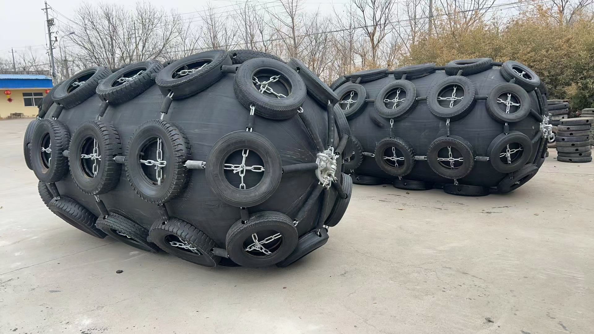
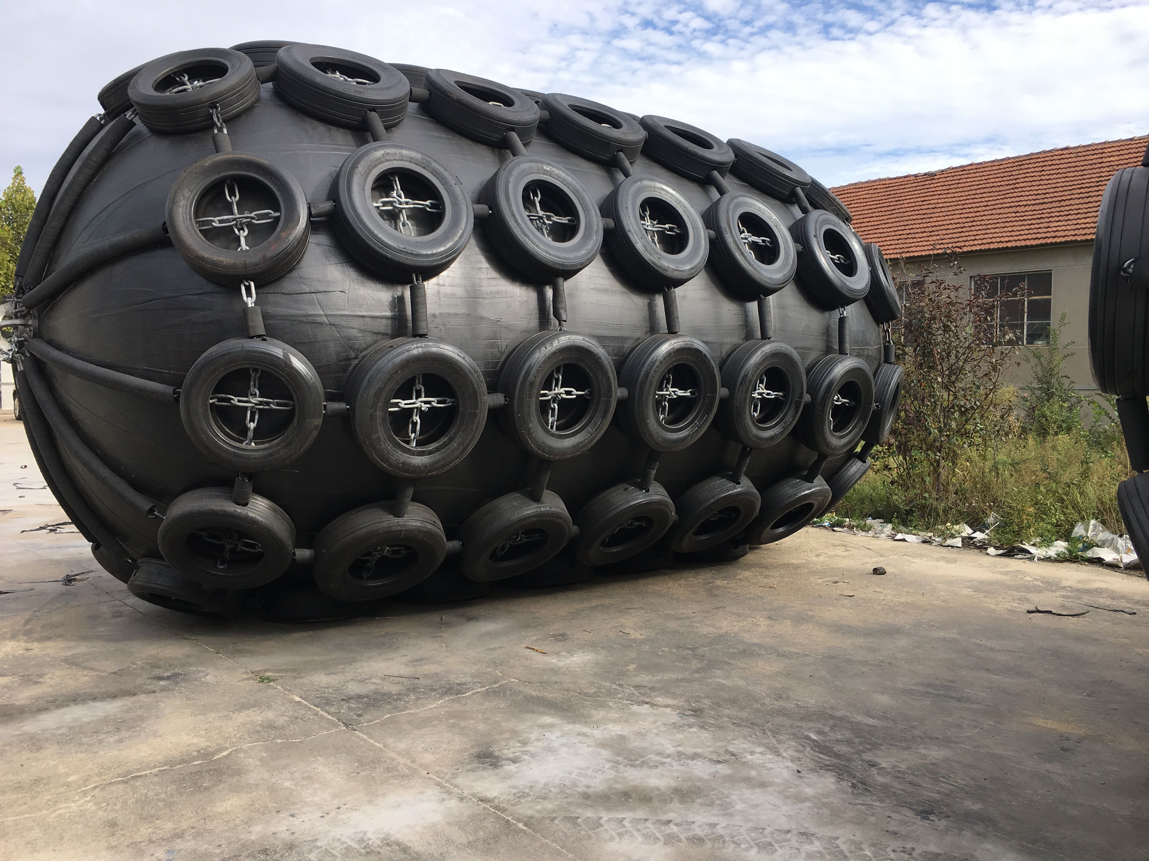
The CTN system wraps the fender body in a protective net of chains and used tires. This configuration offers:
- Maximum abrasion protection for high-contact applications
- Extended service life in demanding port environments
- Suitable for permanent installations with frequent berthing
Typical applications: High-traffic commercial ports, terminals with rough berthing conditions.
Sling type fenders omit the chain-tire-net, instead using reinforced lifting slings attached directly to the fender body. Advantages include:
- Lower weight for easier handling and deployment
- Quick installation and retrieval
- Lower cost than CTN configuration
- Suitable for temporary or semi-permanent use
Typical applications: Offshore STS operations, naval vessels, temporary berthing arrangements.
Selecting the correct fender requires calculating the berthing energy the fender must absorb:
E = ½ × M × V⊃2; × Ce
Where:
- E = Energy to absorb (kJ)
- M = Vessel mass + added mass (typically 1.5-2.0× displacement)
- V = Approach velocity (m/s)
- Ce = Eccentricity coefficient (accounts for berthing angle)
Critical: Most fender manufacturers provide selection software or engineering support. Never rely on simplified tables alone—inaccurate calculations lead to under- or over-specification .
1. Hull Pressure Limits
Pneumatic fenders produce lower hull contact pressures than solid alternatives, but excessive internal pressure can still cause hull stress. Verify vessel hull pressure limits during specification.
2. Environmental Conditions
- Temperature: Standard rubber becomes brittle below -25°C. Specify low-temperature compounds for Arctic operations.
- UV Exposure: Prolonged sunlight degrades rubber. UV-resistant outer layers are essential for floating configurations.
3. Failure Mode Planning
Pneumatic fenders lose all strength immediately if punctured. Unlike foam-filled fenders (which degrade gradually), a punctured pneumatic fender provides zero protection. Consider redundancy in critical applications .
| Interval | Action |
|---|---|
| Pre-operation | Visual inspection, pressure check, valve function |
| Monthly | Detailed surface inspection, chain/net integrity check |
| Annually | Pressure verification, comprehensive structural review |
| Every 3-5 years | Full inspection per ISO 17357 guidelines |
Pressure Loss — Caused by valve failure or puncture. Prevention: Regular valve inspection, protective net coverage.
Surface Cracking — Caused by UV exposure and age. Prevention: UV-resistant compounds, proper storage.
Chain/Net Corrosion — Caused by saltwater exposure. Prevention: Galvanized or stainless components, regular rinsing.
Storage Best Practices: Partially deflate (to 10-20 kPa), store in shaded, ventilated areas away from sharp objects and chemicals.
The global marine rubber fenders market was valued at US$ 567 million in 2024 and is projected to reach US$ 709 million by 2031, growing at a CAGR of 3.3% .
Key growth drivers:
- Port infrastructure development worldwide
- Increasing vessel sizes requiring higher-capacity fenders
- Safety and environmental regulations
- Replacement and maintenance demand
Regional dynamics: Asia-Pacific leads in production, with China serving as a major manufacturing hub for OEM fender production. The region also represents the fastest-growing demand center due to expanding port capacity .
Pneumatic fenders are fully air-filled and float on the water surface, ideal for standard ship-to-ship and ship-to-dock operations. Hydro-pneumatic fenders contain both air and water ballast, maintaining a vertical position to protect submerged hulls—essential for submarine berthing and certain offshore applications .
With proper maintenance, high-quality ISO 17357-compliant fenders typically last 10+ years. Service life depends on contact frequency, environmental exposure, maintenance quality, and storage conditions. CTN configurations generally last longer in high-contact applications .
Yes, with appropriate specifications. Standard rubber compounds become brittle below -25°C. For Arctic or sub-Arctic operations, specify low-temperature modified rubber compounds that maintain elasticity down to -45°C. These formulations prevent cold cracking and maintain full energy absorption performance.
Standard production sizes reach 4.5m diameter × 12m length. Custom sizes are possible but require engineering review. For VLCC STS operations, the standard maximum is 3.3m × 6.5m; larger vessels typically use multiple fenders in configuration rather than single larger units .
For standard sizes from stock: 1-2 weeks. For custom orders: 4-8 weeks depending on size and quantity. Large OEM orders may require 8-12 weeks. Always confirm lead times during procurement planning.
Floating pneumatic rubber fenders represent the most technically advanced and operationally reliable solution for protecting vessels and marine structures during berthing and mooring operations. Their unique combination of low reaction force, high energy absorption, and automatic tidal adjustment makes them the preferred choice for ports, terminals, and offshore facilities worldwide.
As a professional marine fender manufacturer specializing in OEM partnerships, NANJING TAIDUN MARINE EQUIPMENT ENGINEERING CO., LTD produces high-quality pneumatic fenders meeting ISO 17357 standards for global brands, wholesalers, and end-users. Our engineering team provides:
- Custom sizing to match specific operational requirements
- Technical documentation including performance curves and certification
- OEM manufacturing with your branding and specifications
Ready to discuss your fender requirements? Contact our technical team to request specifications, pricing, or engineering support for your next project.


