

Views: 298 Author: NANJING TAIDUN Publish Time: 2026-10-04 Origin: Site
Content Menu
● Introduction: Why Bollard Load Calculation Defines Port Safety
● Understanding Mooring Bollard Fundamentals: Types, Functions, and Terminology
>> What a Mooring Bollard Actually Does
>> Common Bollard Types and Applications
>> Key Terminology: SWL, MBL, and the Safety Hierarchy
● The Two Calculation Approaches: Mariner vs. Civil Engineer
>> The Mariner's Approach: Line-Based Calculation
>> The Civil Engineer's Approach: Displacement-Based Tables
>> Why the Two Approaches Clash (And How to Resolve It)
● Step-by-Step Calculation Methodology for Bollard SWL
>> Step 1: Determine the Design Vessel and Environmental Conditions
>> Step 2: Calculate Environmental Forces on the Moored Vessel
>> Step 3: Determine Mooring Line Configuration and Forces
>> Step 4: Apply Safety Factors and Determine Required SWL
>> Step 5: Verify Against Bollard Product Availability
● Standards and Guidelines: Navigating the Regulatory Landscape
>> Key International Standards for Mooring Bollards
>> The OCIMF MEG-4 Framework: A System Approach
>> Shipboard Bollard Requirements (Classification Societies)
● Advanced Topics: Dynamic Mooring Analysis and Emerging Trends (Added Value Section)
>> When Static Calculation Isn't Enough: Dynamic Mooring Analysis (DMA)
>> New Research on Ultimate Strength of Bollards and Foundations
>> The Role of Material Selection in Life-Cycle Cost
● Practical Selection Guide: From Calculation to Procurement
>> Bollard Selection Checklist for Port Designers
>> Common Specification Mistakes to Avoid
>> 1. What is the difference between SWL and MBL for mooring bollards?
>> 2. How do I calculate the number of bollards required for a berth?
>> 3. What SWL range is typical for commercial port bollards?
>> 4. Can I use the same bollard design for both mooring and towing?
>> 5. How often should mooring bollards be inspected?
>> 6. What factors affect bollard foundation design?
>> 7. Are there international standards for port (shore-side) bollards?
>> 8. What is the "winch rendering" concept and why does it matter for bollard design?
● Conclusion: Engineering Safety into Every Bollard Specification
In every port and berth worldwide, mooring bollards silently carry the critical responsibility of holding multi-thousand-ton vessels against wind, current, and tidal forces. Yet the engineering behind bollard load calculation remains one of the most misunderstood areas in marine infrastructure design. A bollard that's undersized for its application creates catastrophic failure risk—a single fender or bollard failure during a storm can cause hull damage exceeding $500,000 and operational shutdowns lasting weeks.
The challenge facing port engineers, procurement managers, and shipbuilders is that two distinct calculation methodologies exist: the "mariner's approach" based on mooring line breaking loads, and the "civil engineer's approach" based on vessel displacement tables. These approaches can produce dramatically different bollard specifications—sometimes with a gap of 300% or more in calculated load requirements.
This guide bridges that gap. We'll walk through the step-by-step engineering process for calculating mooring bollard requirements, explain the governing standards (ISO, BS 6349, OCIMF MEG-4), and provide practical selection criteria for B2B procurement. Whether you're specifying bollards for a new container terminal, upgrading an existing berth, or sourcing OEM bollards for vessel construction, this analysis will give you the technical foundation to specify with confidence.
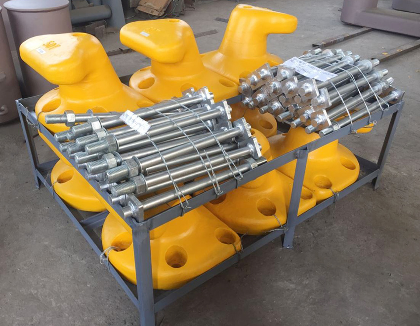
A mooring bollard is a sturdy vertical post anchored to a dock, quay, or ship deck. Its fundamental purpose is to secure ropes or cables that keep vessels firmly in place against drift from wind, waves, or tides. The bollard transmits line pull forces into the supporting structure—whether that's a concrete quay wall, a steel dolphin, or a ship's deck.
Key distinction: Bollards differ from cleats (smaller, lighter vessels), bitts (often double-post configurations), and quick-release hooks (specialized for specific line types). For commercial port applications, double bitt bollards and cruciform bollards are the dominant types.
| Type | Configuration | Best Application | Typical SWL Range |
|---|---|---|---|
| Single Bitt (Pillar) | Single vertical post | Steep rope angles, variable tides | 5–100 tonnes |
| Double Bitt (Twin Horn) | Two posts with crossbar | Larger vessels, multiple lines | 50–300+ tonnes |
| Cruciform | Four-way cross shape | Shipboard use, tanker manifolds | 30–200 tonnes |
| T-Head | Horizontal bar on top | High loads, varied rope angles | 100–500+ tonnes |
| Kidney | Oval with curved lip | Gentle on ropes, mild tidal ranges | 20–150 tonnes |
*Sources: industry bollard classification and shipboard application standards*
Before calculating bollard requirements, you must understand the safety hierarchy that governs mooring system design:
- MBL (Minimum Breaking Load): The certified breaking strength of a mooring line
- SWL (Safe Working Load): The load limit for mooring purposes, marked on each bollard
- SDMBL (Ship Design Minimum Breaking Load): The primary parameter for sizing all mooring equipment on a vessel
- MHC (Maximum Holding Capacity): The load at which a winch brake renders (typically 50–60% of MBL)
Critical safety principle: The winch brake is designed to be the weakest point in the mooring system. It should render before the mooring line breaks, and the line should break before the bollard fails. This hierarchy ensures controlled failure rather than catastrophic structural collapse.
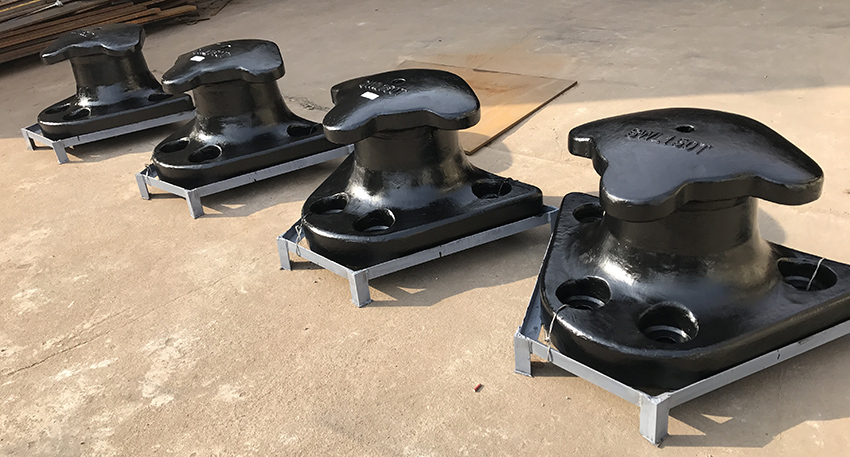
Mariners traditionally calculate bollard requirements based on the mooring lines they intend to use. The logic is straightforward: if a bollard must hold three mooring lines, each with an MBL of 130 tonnes, the bollard SWL should theoretically be 390 tonnes (3 × 130).
The problem: Bollards of this capacity are not commercially available and would require massive foundations that are impractical for most quay walls. This approach, while intuitively appealing, doesn't reflect how mooring systems actually behave in service.
Civil engineers use design tables from standards like BS 6349 and national port design codes that relate vessel displacement to required bollard loads. These tables account for:
- Environmental forces (wind, current, waves)
- Vessel geometry and windage area
- Mooring line configuration
- Safety factors for extreme conditions
The Port of Rotterdam Authority has adopted this approach for new builds, using displacement-based calculations adjusted for site-specific conditions.
The fundamental disconnect is this: mariners think in terms of line strength; civil engineers think in terms of structural capacity. The resolution lies in understanding how mooring systems actually work in operation:
1. Normal conditions: Winches on auto-tension apply relatively low holding forces (typically 30 tonnes maximum for the largest vessels)
2. Deteriorating conditions: Winches switch to brake mode, increasing holding capacity
3. Storm conditions: Winches render at their MHC (50–60% of MBL), redistributing loads
Key insight: The maximum load a bollard will experience in service is not the sum of all line MBLs, but rather the load at which the winch brakes render—typically 50–60% of the line MBL. This is why a 130-tonne MBL line effectively transmits only 65–78 tonnes to the bollard under worst-case rendering conditions.
The practical resolution: For bollard design, use the winch rendering load as the design basis, not the line breaking load. This produces specifications that are both safe and constructible.
Start with the largest vessel your berth will accommodate and the worst-case environmental conditions:
- Vessel displacement (fully loaded and ballast conditions)
- Wind area (frontal and lateral)
- Maximum wind speed (typically 30–60 knots for design)
- Maximum current speed (at bow and stern, ±10°)
- Wave exposure (if applicable)
BS 6349-4:2026 provides guidance for vessels with minimum displacement of 1,000 tonnes. For smaller vessels, simplified methods may apply.
The primary environmental forces acting on a moored vessel are:
Wind Force:
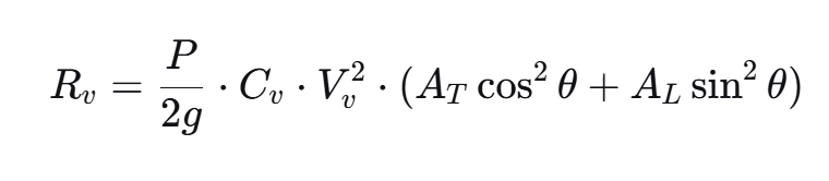
Where:
P= air density
Cv= wind force coefficient (depends on vessel type and loading)
Vv = wind velocity
AT = transverse wind area
AL= longitudinal wind area
Current Force: Similar formulation with water density and current velocity.
Combined Loading: For design purposes, environmental forces are combined using load combination factors that account for the reduced probability of simultaneous extreme events.
The number, type, and arrangement of mooring lines determine how environmental forces distribute to individual bollards:
- Line count: Typically 4–16 lines for commercial vessels
- Line angles: Horizontal and vertical angles affect force resolution
- Line elasticity: Synthetic lines stretch, affecting load distribution
- Winch settings: Auto-tension vs. brake mode changes holding capacity
Critical calculation: Determine the maximum force per bollard based on line geometry and winch rendering characteristics.
Standards such as BS 6349 and classification society rules specify safety factors for bollard design:
- Serviceability Limit State (SLS): Maximum expected operational load
- Ultimate Limit State (ULS): Factored loads (typically 1.5× SLS) for structural design
- Accidental Limit State (ALS): Extreme events with reduced factors
Recommended approach: Use the winch rendering load (50–60% of line MBL) as the SLS load, then apply appropriate factors for foundation design.
After calculating required SWL, verify against available bollard products:
- Standard SWL ranges: Commercial port bollards typically range from 10 to 200 tonnes
- Custom capacities: Larger bollards (300–500+ tonnes) require custom fabrication
- Foundation requirements: Higher SWL bollards require proportionally larger foundations
Bollard spacing rule of thumb: Space bollards at 15–30 meters or approximately 15% of the shortest ship length to accommodate typical mooring patterns.
The Oil Companies International Marine Forum (OCIMF) Mooring Equipment Guidelines (MEG-4) provides the most comprehensive framework for mooring system design:
Key parameters:
- SDMBL: Ship Design Minimum Breaking Load—the foundation of all equipment sizing
- Winch SWL = SDMBL
- Brake rendering point = 60% of SDMBL
- Bollard/fairlead SWL = SDMBL
- Mooring line LDBF = 100–105% of SDMBL
- Tail TDBF = 125–130% of SDMBL
Operational limits:
- Maximum recommended working load for lines: 22% of SDMBL
- Working Load Limit (WLL): 50% of SDMBL
Retirement criteria: Lines and tails should be retired when residual strength drops to 75% of SDMBL.
For shipboard bollards, classification rules specify:
- Double bollards: Diameter ≥ 10× mooring line diameter, minimum 300mm
- SWL marking: By weld bead or equivalent on deck fittings
- Load application point: Not less than 4/5 of tube height above base
- Figure-of-eight attachment: SWL should be twice the MBL of mooring lines per conventional design
Tanker-specific requirements: Double bollards minimum 300mm diameter forward and aft of cargo manifold; cruciform bollards minimum 600mm height near manifold centerline.
For complex or high-risk mooring situations, static calculations may be insufficient. Dynamic Mooring Analysis (DMA) is a computer-based simulation that calculates:
- Vessel motions under wind, wave, current, and passing vessel forces
- Maximum loads on individual mooring points
- Time-domain responses to transient events
- Fatigue accumulation on lines and fittings
When DMA is recommended:
- Large container vessels (>10,000 TEU) with high windage
- Exposed berths with significant wave action
- LNG/LPG carriers with specialized mooring requirements
- Sites with strong passing vessel effects
Limitation: DMA is complex and expensive, typically not performed for every project or during preliminary design. Use static methods for initial sizing, DMA for final verification of critical applications.
Recent research (2010) published in *Ocean Engineering* investigated the ultimate load capacity of mooring bollards and their hull foundation structures. Key findings:
- Local hull stresses often exceed fitting stresses: For most mooring fittings, the SWL is limited by hull strength, not the fitting itself
- Reinforcements based on allowable stress design: May increase production costs without significantly raising ultimate capacity
- Ultimate Strength Design (USD) vs. Allowable Stress Design (ASD): Different criteria can produce different capacity assessments
Procurement implication: When specifying bollards, consider foundation design as part of the total system. A high-capacity bollard on an inadequate foundation is a failure waiting to happen.
Bollard material choice affects 10–20 year total cost of ownership:
| Material | Corrosion Resistance | Maintenance | Typical Application |
|---|---|---|---|
| Cast Steel | Moderate | Regular painting | General port use |
| Ductile Iron | Good | Less frequent repainting | Marine environments |
| Stainless Steel | Excellent | Minimal | Premium/chemical exposure |
| Welded Steel | Variable | Coating dependent | Shipboard, custom |
Recommendation: Choose materials and coatings for your water type (salty, brackish), maintenance plan, and expected service life. Ductile iron often provides the best balance of corrosion resistance and cost for marine applications.
When specifying or procuring mooring bollards, confirm these items:
- [ ] Design load / SWL: Request tested working load and safety factor documentation
- [ ] Type and shape: Match to vessel types and mooring angles
- [ ] Material and coating: Choose for local corrosion risk and maintenance intervals
- [ ] Mounting and foundation: Ensure deck or quay can take dynamic loads
- [ ] Spacing and layout: Follow 15–30m spacing rule; coordinate with fender positions
- [ ] Inspection and spare parts: Plan routine checks; keep bolts/anchors on hand
- [ ] Certification: Request material certificates and load test reports
1. Specifying SWL based on line MBL sum: This produces impractical, unavailable specifications. Use winch rendering load instead.
2. Ignoring foundation capacity: A 200-tonne bollard on a 100-tonne foundation fails at 100 tonnes.
3. Overlooking dynamic effects: Passing vessels and wave action can produce loads exceeding static calculations.
4. Choosing bollards on price alone: Life-cycle cost includes maintenance, repainting, and replacement frequency.
5. Skipping inspection planning: Bollards require routine inspection for loose bolts, cracked welds, and corrosion.
SWL (Safe Working Load) is the maximum load limit for mooring purposes, marked on each bollard. MBL (Minimum Breaking Load) is the certified breaking strength of a mooring line. The bollard's SWL should be at least equal to the SDMBL (Ship Design Minimum Breaking Load), but practical designs consider winch rendering loads rather than line breaking loads.
Bollard quantity depends on vessel length, mooring pattern, and line angles. A practical guideline is 15–30 meter spacing along the berth face, or approximately 15% of the shortest ship length you expect to moor. For naval facilities, 60-foot (18.3m) centers provide flexibility for multiple vessel types.
Commercial port bollards typically range from 10 to 200 tonnes SWL, with larger custom bollards available up to 500+ tonnes for VLCC terminals. Shipboard bollards are generally smaller, with capacities matched to the vessel's mooring line specifications.
While some bollards serve dual purposes, towing and mooring have different load requirements. If a bollard will be used for towing, the TOW (Towing load limit) must be marked in addition to SWL, and the design must account for the higher dynamic loads associated with towing operations.
Routine visual inspection should occur monthly or after severe weather events. Detailed inspection (including weld examination, bolt torque checks, and corrosion assessment) is recommended annually. Bollards in high-use or exposed locations may require more frequent inspection.
Foundation design depends on bollard SWL, load direction, soil conditions, and structural configuration. The foundation must resist horizontal pull loads (typically applied from 0 to 180 degrees in plan) and vertical components from line angles. For critical applications, dynamic mooring analysis may be required to determine actual load distributions.
BS 6349-4:2026 provides recommendations for fendering and mooring systems design in maritime works, including bollard calculations for vessels with minimum 1,000 tonnes displacement. PIANC guidelines and national port design codes also provide calculation methodologies. Shipboard bollards are covered by ISO 13795 and ISO 13797.
Winch rendering is the controlled release of mooring line tension when the winch brake reaches its Maximum Holding Capacity (MHC)—typically 50–60% of the line MBL. This matters because it means the maximum load transmitted to a bollard is limited by the winch rendering load, not the line breaking load. Designing bollards for winch rendering loads produces practical, constructible specifications.
Mooring bollard calculation is not a one-size-fits-all exercise. It requires understanding vessel characteristics, environmental forces, mooring system behavior, and the safety hierarchy that governs all components. The key takeaways for B2B procurement and design professionals are:
1. Use the winch rendering load (50–60% of line MBL) as the design basis, not the sum of line breaking loads
2. Follow BS 6349 and OCIMF MEG-4 frameworks for systematic calculation
3. Verify product availability against calculated SWL requirements—capacities above 200 tonnes require custom fabrication
4. Consider foundation design as part of the total system; local hull stresses often govern
5. Plan for inspection and maintenance to ensure long-term safety and performance
The right bollard specification balances safety, constructibility, and life-cycle cost. Engage suppliers who can provide certified load data, material certificates, and installation guidance—not just a catalog price.
Ready to specify mooring bollards for your project? Contact our engineering team for a free application assessment and SWL calculation tailored to your vessel mix, environmental conditions, and berth configuration. We provide OEM mooring bollards with full documentation, testing certification, and global delivery.


