

Views: 343 Author: NANJING TAIDUN Publish Time: 2026-10-05 Origin: Site
Content Menu
● Introduction: Why Retrofit Planning Defines Success
● What Is a Mooring Bollard Retrofit? Defining Scope and Objectives
>> Why Retrofits Fail: Evidence Gaps
● The Evidence-First Framework: What to Collect Before Design Begins
>> Essential Documentation Checklist
>> When Existing Evidence Is Missing
● Load Determination: Engineering the Design Basis
>> Bollard Load Calculation Methodology
>> Design Load Factors for Retrofits
● Anchorage Design: The Critical Structural Interface
>> Pattern-Matched vs. New Anchorage Approaches
>> Chemical Anchor Design Considerations
● Installation Sequencing for Operating Docks
>> Planning Work Around Active Berthing Operations
>> Work Zone Isolation and Safety Controls
● Quality Verification: Inspection, Testing, and Handover Evidence
>> Non-Destructive Testing Methods
>> Inspection Frequency Guidelines
● OEM Procurement Considerations: Sourcing Bollards for Retrofit Projects
>> Bollard Material and Certification Requirements
>> Supplier Capability Assessment
>> 1. Can I replace a mooring bollard without replacing the concrete foundation?
>> 2. What is the difference between pattern-matched and new anchorage retrofit?
>> 3. What design loads should I use for a mooring bollard retrofit?
>> 4. How often should mooring bollards be inspected?
>> 5. What causes mooring bollard failures?
>> 6. Can mooring bollard retrofit work be performed while the dock remains operational?
>> 7. What documentation should be required for bollard retrofit handover?
>> 8. How do I select the right bollard material for a retrofit?
● Conclusion: Engineering-Led Retrofit Delivers Long-Term Reliability
Retrofitting a mooring bollard onto an existing concrete dock is not a catalogue selection exercise. It is a structural engineering challenge that demands evidence-based decisions at every stage. Too often, port authorities and terminal operators approach bollard replacement or addition as a simple procurement task—only to discover mid-project that the existing anchorage is inadequate, the concrete has deteriorated, or the design loads exceed original assumptions.
The consequences of poor retrofit planning are severe. Mooring cleat failures have caused fatalities, vessel damage, and berth closures. In one documented case, inadequate under-deck stiffening combined with corroded holding-down bolts led to catastrophic fitting failure during berthing operations.
This guide provides a systematic, engineering-first framework for mooring bollard retrofit projects on existing concrete docks. We'll cover the critical evidence collection phase, load determination methodology, anchorage design considerations, and installation sequencing for operating terminals. Whether you represent a port engineering department, a marine construction contractor, or an equipment supplier seeking OEM partnerships, this analysis delivers the practical intelligence needed to de-risk your retrofit project.
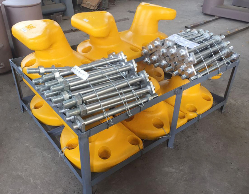
Mooring bollard retrofit encompasses three distinct project scenarios, each with different engineering requirements:
1. Pattern-Matched Replacement: New bollard with base-plate bolt pattern matching existing concrete holes. This approach avoids new penetrations and may reuse existing anchorage studs or sleeves.
2. New Anchorage Retrofit: Different bollard interface or increased Safe Working Load (SWL) requiring new anchor holes, typically using chemical anchors or cast-in-place solutions.
3. Bollard Addition: Installing additional mooring points on an existing berth, requiring new foundation design and load-path verification.
Critical distinction: Pattern-matched replacement is only viable when the existing bolt-hole positions are precisely known, the replacement bollard can be manufactured to match, and the retrofit does not increase required SWL.
The most common failure mode in bollard retrofit projects is proceeding to design without adequate existing-condition evidence. Key information that must be verified before any engineering begins includes:
- Existing fitting records: Original bollard type, SWL, manufacturer, installation date
- Foundation details: Concrete grade, thickness, reinforcement position, anchorage type
- Condition assessment: Corrosion, cracking, spalling, bolt integrity
- Load history: Previous SWL requirements, any modifications or repairs
Without this evidence, the retrofit design becomes speculative—and speculative designs create liability.
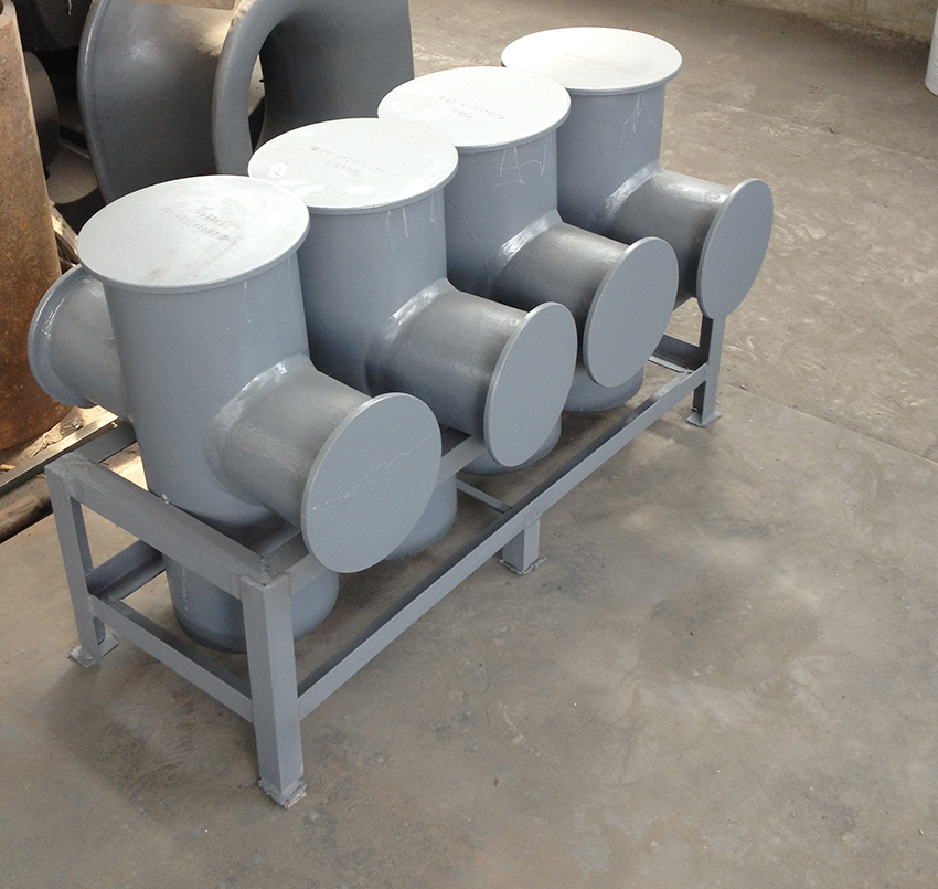
Before engaging a structural engineer, compile the following existing-condition evidence package:
| Evidence Category | Required Documents | Priority |
|---|---|---|
| Original Design | As-built drawings, bollard specification sheets | Critical |
| Installation Records | Anchor type, embedment depth, grout specifications | Critical |
| Inspection History | Previous NDT reports, maintenance records | High |
| Condition Assessment | Current photographs, corrosion mapping, concrete survey | High |
| Operational Requirements | Vessel sizes, berthing frequency, environmental loads | Critical |
Professional insight: Request existing bollard photographs, original drawings, inspection records, and bolt-interface status before any design begins. If the intended SWL of the new bollard exceeds the original, this must be flagged immediately as it fundamentally changes the retrofit scope.
In many retrofit projects—especially on aging infrastructure—complete documentation may not exist. In these cases, physical investigation becomes necessary:
1. Concrete coring: Determine actual concrete grade, thickness, and reinforcement layout
2. Anchor pull-out testing: Verify existing anchorage capacity through field testing
3. Dimensional survey: Measure existing bolt patterns, base-plate dimensions, and elevations
4. Material testing: Assess remaining service life of existing components
Decision point: If existing anchorage cannot be verified as adequate for the required SWL, a new anchorage design is mandatory—no exceptions.
Bollard design loads must be determined through recognized methodologies. The BS6349-4 standard provides five methods for determining probable maximum loadings on bollards, including:
- Simple share loads: For berths with six mooring points, one-third of total transverse force per point; for four points, one-half per point
- Elastic system analysis: Treating mooring lines as elastic elements with hand calculation or computer analysis
- Dynamic Mooring Analysis (DMA): Recommended where wave forces or vessel-wave interaction is significant
Notional load capacities from BS6349-4 for preliminary design:
| Vessel Displacement | Mooring Point Load |
|---|---|
| 20,000 – 50,000 tonnes | 80 tonnes |
| 50,000 – 100,000 tonnes | 100 tonnes |
| 100,000 – 200,000 tonnes | 150 tonnes |
| Above 200,000 tonnes | ≥ 200 tonnes |
For retrofit projects, the design load applied to supporting structures should incorporate safety factors:
- Normal towing operations: 1.25× the intended maximum towing load
- Escort or other towing operations: Greater of breaking load of tow line or 1.25× safe towing load
- Mooring fittings: 1.15× the greater of breaking load of mooring line or SWL
Allowable stresses under design load conditions: 100% of minimum yield stress for normal conditions, 60% for combined bending and shear.
The choice between pattern-matched replacement and new anchorage retrofit is the single most consequential engineering decision in the project.
Pattern-Matched Replacement is viable when:
- Existing bolt-hole positions are precisely known and documented
- Replacement bollard can be manufactured with matching base-plate pattern
- Retrofit does not increase required SWL
- Existing anchorage or sleeves are verified as sound
New Anchorage Retrofit is required when:
- Existing bolt pattern is unknown or undocumented
- New bollard has different interface dimensions
- Required SWL increases beyond original design
- Existing anchorage is compromised
For new anchor installations into existing concrete, chemical (adhesive) anchors are commonly used. Critical design parameters include:
1. Concrete grade and condition: Minimum concrete strength required per anchor manufacturer
2. Embedment depth: Determined by design tension and shear loads
3. Hole preparation: Drilling method, cleaning procedure, moisture conditions
4. Design loads per bolt: Tension, shear, and moment from bollard loading
Installation sequence for chemical anchors:
1. Drilling/coring: Align drill bit perpendicular, use water flow for cooling
2. Hole cleaning: Pressurized water, steel brush, oil-free compressed air (minimum 6 bar)
3. Adhesive injection: Start from bottom of hole, avoid air voids
4. Anchor setting: Insert anchor with twisting motion, maintain alignment
5. Curing: Do not load until specified curing time achieved
Quality control checkpoint: Verify hole depth, diameter, and cleanliness before adhesive injection. Contaminated holes are the leading cause of chemical anchor failure.
A retrofit on an operating dock must be planned so the work does not prevent berthing, create safety hazards, or damage existing structures. The planning sequence follows five gated stages:
1. Define records: Gather existing fitting, dock, and operating information
2. Review scope: Establish engineering and owner review boundaries
3. Agree controls: Document dock operation, access, and local requirements
4. Execute approved work: Follow project-specific method and hold points
5. Inspect and hand over: Compile agreed records and acceptance package
Owner approval requirements before scheduling installation:
- Written approval of retrofit design and supporting calculations
- Confirmed berth shutdown or access window
- Agreed method statement, outage plan, and acceptance criteria
For live-dock work, the contractor must:
- Coordinate with terminal operator for access, crane availability, and permits
- Isolate work zone with barriers
- Prevent use of active berth until new bollard is installed and accepted
- Follow owner-approved method statement, permits, and operational controls
Safety alert reference: A UK Maritime and Coastguard Agency safety alert documented mooring cleat failures caused by inadequate under-deck stiffening, corroded holding-down bolts, and absence of planned maintenance regimes. The alert emphasizes that fittings must be of adequate strength, adequately stiffened, and adequately secured—with annual inspection of mild steel bolts and replacement every two years or conversion to stainless steel.
Agree required documentation before contract placement. Product records may include:
- Material test certificates
- Non-destructive testing (NDT) reports
- Dimensional inspection records
- Hot-dip galvanizing certificates
- Coating thickness reports
For condition assessment and post-installation verification:
- Ultrasonic testing: Internal crack detection
- Magnetic particle inspection: Surface and near-surface defects
- Visual inspection: Cracks, corrosion, deformation on head and base
- Anchor bolt inspection: Rust, movement, coating integrity
| Application | Recommended Interval |
|---|---|
| Standard docks | Every 6–12 months |
| Heavy-duty terminals | Every 3–6 months |
| After extreme weather | Immediate inspection |
Maintenance best practices:
- Monthly visual checks for corrosion or structural cracks
- Bi-monthly deep cleaning to remove salt deposits
- Quarterly lubrication of moving parts with marine-grade lubricant
- Prompt repair of any detected damage
- Professional replacement when beyond repair
For retrofit projects, bollard material selection impacts both performance and corrosion resistance:
| Material | Application | Corrosion Resistance |
|---|---|---|
| Cast Iron | Standard duty | Moderate |
| Cast Steel | Heavy duty | Good |
| Ductile Iron | High strength | Good |
Certification requirements: K-head dock bollards should comply with industry standards such as IACS and ASCE, with available certifications including CCS, ABS, BV, LR, NK, and RINA.
For OEM procurement, evaluate suppliers on:
1. Production capacity: Loading capacity range (15T to 200T typical for K-head bollards)
2. Material traceability: Documentation chain from raw material to finished product
3. Testing facilities: In-house NDT, dimensional verification, load testing
4. Customization capability: Base-plate pattern matching, dimensional modifications
5. Certification portfolio: Classification society approvals for target markets
Procurement insight: For retrofit projects, the supplier must confirm that the new bollard base-plate thickness, hole diameter, and overall dimensions match the original interface before proceeding with manufacture.
Yes, if the existing anchorage is verified as sound and the new bollard has a matching base-plate pattern. Pattern-matched replacement avoids new penetrations and may reuse existing anchorage studs or sleeves. However, if the required SWL increases or existing anchorage is compromised, new anchor installation is mandatory.
Pattern-matched replacement uses the existing bolt-hole pattern in the concrete and requires a custom bollard manufactured to match. New anchorage retrofit involves drilling new holes and installing new anchors, required when the existing pattern is unknown, the new bollard has a different interface, or the required SWL increases.
Design loads depend on vessel displacement and berthing conditions. BS6349-4 provides notional load capacities: 80 tonnes for vessels 20,000-50,000 tonnes, 100 tonnes for 50,000-100,000 tonnes, and 150 tonnes for 100,000-200,000 tonnes. For towing applications, apply 1.25× the maximum towing load.
Standard docks: every 6–12 months. Heavy-duty terminals: every 3–6 months. After extreme weather events: immediate inspection. Monthly visual checks are recommended for corrosion and structural cracks.
Common failure causes include: inadequate under-deck stiffening, corroded holding-down bolts, absence of planned maintenance, and excessive force during berthing operations. Regular inspection and adherence to design load limits are essential preventive measures.
Yes, with proper planning. The work may need to be scheduled during a berth closure window or performed in staged phases so adjacent berths remain available. Owner approval of the method statement and outage plan is required before work begins.
Required documentation may include: material test certificates, NDT reports, dimensional inspection records, galvanizing certificates, coating thickness reports, and as-built drawings showing final anchor positions and elevations.
Consider: required SWL, environmental exposure, and compatibility with existing infrastructure. Cast steel or ductile iron offer better corrosion resistance and strength for marine environments. Coating systems (paint or galvanization) provide additional protection.
Mooring bollard retrofit on existing concrete docks succeeds when approached as a structural engineering project, not a product purchase. The evidence-first framework—documenting existing conditions, determining design loads, engineering the anchorage interface, and planning installation around operational constraints—is what separates successful retrofits from costly failures.
Key takeaways for project success:
- Collect evidence before design: Existing drawings, inspection records, and physical investigation are prerequisites, not optional extras
- Determine loads rigorously: Use recognized standards (BS6349-4, UFC 4-159-03) and apply appropriate safety factors
- Engineer the anchorage: Pattern-matched replacement requires verified dimensions; new anchorage requires structural design
- Plan for live-dock operations: Owner approval, method statements, and staged execution are essential for operating terminals
- Verify through inspection: Agreed documentation and NDT testing confirm that the installed system meets design requirements
The procurement bottom line: Specify based on calculated design loads, verified existing conditions, and engineering review—not catalogue selection or lowest price. Engage suppliers who can provide documentation, testing certification, and application engineering support.
Ready to plan your mooring bollard retrofit? Contact our engineering team for a project-specific assessment and OEM bollard manufacturing consultation. We provide full documentation, testing certification, and global delivery for marine infrastructure projects.


