

Views: 246 Author: Nanjing Taidun Publish Time: 2026-11-06 Origin: Site
Content Menu
● What Does the Energy Absorption to Reaction Force Ratio Mean?
>> Why Fender Size Can Distort the Comparison
● Yokohama Pneumatic Fender vs Foam Filled Fender: How They Work
>> Pneumatic Fenders: Compressed Air Inside a Reinforced Rubber Body
>> Foam-Filled Fenders: A Resilient Core with a Protective Skin
● Published Pneumatic Fender Data: What the Ratio Actually Shows
>> Why There Is No Universal Foam-Filled Comparison Number
● Three Engineering Checks That Matter More Than a Headline Ratio
>> 1. Check Reaction Force at the Required Energy
>> 2. Separate Total Reaction Force from Hull Pressure
>> 3. Compare Conservative, Tolerance-Adjusted Performance
● Practical Selection Matrix for OEM Buyers
● A Six-Step Workflow for Comparing Supplier Quotations
>> Step 1: Define the Berthing Duty
>> Step 2: Establish Allowable Loads
>> Step 3: Request Comparable Performance Curves
>> Step 4: Check Geometry and Angled Contact
>> Step 5: Verify Quality Documentation
>> Step 6: Compare Lifecycle Cost
● OEM Procurement with Nanjing Taidun
>> 1. Which has a better energy absorption to reaction force ratio?
>> 2. Is a higher E/R ratio always safer?
>> 3. Does an 80 kPa pneumatic fender always outperform a 50 kPa version?
>> 4. Are foam-filled fenders maintenance-free?
>> 5. Does ISO 17357-1 cover foam-filled fenders?
>> 6. Can OEM pneumatic fenders be marketed as genuine Yokohama products?
● Request an Application-Based OEM Proposal
At Nanjing Taidun Marine Equipment Engineering Co., Ltd., we support overseas brands, wholesalers, and manufacturers with OEM marine equipment. For buyers comparing floating fenders, one question deserves particular attention: "Yokohama Pneumatic Fender vs Foam Filled Fender: Energy Absorption to Reaction Force Ratio"—which solution absorbs the required berthing energy without imposing excessive loads on the vessel or berth?
The engineering answer is not a universal winner. Pneumatic and foam-filled fenders can both deliver high energy absorption with relatively low reaction forces. The better choice depends on size, operating conditions, performance curves, and maintenance requirements.
Our procurement perspective is straightforward: compare verified performance at the same operating conditions, then evaluate the complete system—not just the headline ratio.
Terminology matters, too. Yokohama is a manufacturer's brand. Although "Yokohama-type" commonly describes pneumatic fenders in commercial searches, independently manufactured OEM products should not be represented as genuine Yokohama products.

Energy absorption measures the work a fender accepts as it compresses. Reaction force measures the load it transfers back to the vessel and supporting structure.
Their relationship can be expressed as:
E/R=Energy absorption, kJ/Reaction force, kN
Because one kilojoule equals one kilonewton-metre, the resulting unit is metres.
A higher E/R value means more energy absorption per unit of stated reaction force. However, it is not a dimensionless efficiency percentage, nor does it independently establish safety.
Energy depends on the entire force–deflection curve:
E=∫0δR(x)dx
Here, \(\delta\) is compression distance. Two fenders with identical maximum reaction forces may absorb different amounts of energy because their force–deflection curves differ.
Larger fenders generally provide more compression travel. Consequently, comparing a large pneumatic fender with a smaller foam-filled fender can produce a misleading conclusion about material superiority.
For a meaningful comparison, align:
- Fender diameter and effective length.
- Deflection and available clearance.
- Loading direction and contact geometry.
- Temperature and compression speed.
- Performance tolerances and test methods.
The useful question is not simply "Which type has the highest ratio?" It is "Which verified configuration satisfies our energy, load, clearance, and operating requirements?"
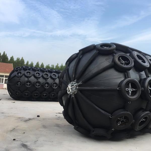
Pneumatic fenders absorb energy as their enclosed air compresses and the reinforced rubber body deforms.
Their construction typically includes an outer rubber layer, reinforcement, and an inner airtight layer. Depending on the design, they may use a chain-and-tyre net or a sling-type arrangement.
Initial internal pressure influences performance. Common high-pressure product categories include 50 kPa and 80 kPa configurations.
Increasing initial pressure can increase energy absorption within the same nominal dimensions. It also increases reaction force and hull pressure. Therefore, choosing a higher-pressure version is not automatically an improvement for a pressure-sensitive vessel.
Foam-filled fenders absorb energy through compression of a resilient closed-cell foam core. A reinforced elastomeric outer skin protects the core against service damage.
They do not depend on maintaining an inflated air chamber. Foam grade, construction, skin reinforcement, and dimensions influence their performance.
Low-reaction and higher-capacity configurations are available. Consequently, "foam-filled fender" describes a product family—not one universal energy-to-reaction characteristic.
Their resistance to deflation is an important operational advantage. Nevertheless, skin damage, attachment deterioration, and core condition still require attention.
Yokohama publishes the following figures for its nominal 2,000 × 3,500 mm floating pneumatic fenders.
| Configuration | Guaranteed energy absorption | Reaction force at GEA | Calculated E/R | Hull pressure at GEA |
|---|---|---|---|---|
| Initial pressure: 50 kPa | 308 kJ | 875 kN | 0.352 m | 128 kPa |
| Initial pressure: 80 kPa | 430 kJ | 1,150 kN | 0.374 m | 168 kPa |
For this specific size, moving from 50 kPa to 80 kPa increases energy absorption by approximately 40%. Reaction force rises by approximately 31%, while E/R improves by only around 6%.
That distinction matters. A buyer focusing exclusively on the additional energy could overlook the substantially higher load transferred to the vessel.
These are published Yokohama product figures, not Nanjing Taidun test results or a performance guarantee for another manufacturer.
A defensible foam comparison requires a specific model and grade, supported by its corresponding performance table.
Matching external dimensions alone is insufficient. Different foam grades can change both absorbed energy and reaction force.
For an OEM quotation, request the actual proposed foam configuration and calculate its E/R using values measured at the same declared compression point.
A generic claim that either technology "always has a better ratio" is not a reliable purchasing basis.
Catalogue endpoints are useful, but a berth may operate below the fender's rated energy.
Ask suppliers to identify the compression and reaction force corresponding to your required design energy—not only the maximum catalogue values.
This reveals how the proposed fender behaves during the operating event that matters to your project.
It also prevents comparisons between one product's rated endpoint and another product's partial-compression condition.
Reaction force is a total load. Hull pressure describes how that load is distributed over contact area.
A fender can have an acceptable total reaction while still creating an unsuitable local contact condition.
Review:
- Vessel shell-plating limitations.
- Actual contact area and geometry.
- Hull curvature and protrusions.
- Protective net or skin contact.
- Supporting structures and connections.
Neither E/R nor average hull pressure alone proves that local vessel stresses are acceptable.
Manufacturing and test tolerances affect procurement decisions.
Where a supplier declares applicable energy and reaction tolerances, evaluate the minimum acceptable energy and maximum acceptable reaction together.
For example, a hypothetical quotation showing 300 kJ and 800 kN has a nominal E/R of 0.375 m. If its declared tolerances permit 10% less energy and 10% more reaction, the conservative combination becomes 270 kJ and 880 kN, or approximately 0.307 m.
This is an illustrative calculation, not a universal tolerance rule. Apply the specific guarantees and acceptance criteria in the contract.
| Selection factor | Pneumatic fender | Foam-filled fender |
|---|---|---|
| Energy-absorbing mechanism | Compressed air and body deformation | Resilient foam compression |
| Main performance variables | Size, pressure, construction | Size, foam grade, construction |
| Inflation management | Pressure checks required | No inflation-pressure checks |
| Damage considerations | Leakage can affect performance | Skin and core damage still require assessment |
| Performance evidence | GEA, reaction, pressure, curves, applicable tests | Energy, reaction, grade, curves, applicable tests |
| Suitable procurement approach | Verify pressure-specific performance | Verify grade-specific performance |
Neither column eliminates the need for engineering review. Accessories, installation details, inspection access, and replacement arrangements can change the practical outcome.
Provide vessel information, berth arrangement, approach conditions, tidal variation, and expected operating frequency.
Have the responsible designer establish normal and abnormal berthing-energy requirements. Vessel deadweight alone is not a sufficient design input.
Identify allowable hull pressure, supporting-structure capacity, and relevant connection loads.
Do not select a fender solely because its stated energy exceeds the requirement.
Require energy–deflection and reaction–deflection information for each proposed configuration.
Ask suppliers to state pressure or foam grade, test conditions, and applicable corrections.
Review available compression travel, stand-off, hull clearance, tide, and relative vessel movement.
Do not transfer a manufacturer's angular-performance claim to another product without supporting evidence.
For high-pressure pneumatic fenders, specify the applicable ISO 17357-1 requirements and request relevant supporting documentation.
Do not automatically apply that pneumatic-fender standard to foam-filled products. Define the foam product's applicable test methods and acceptance criteria separately.
Include purchase price, freight, handling, inspection, accessories, repair options, downtime exposure, and replacement planning.
The lowest initial quotation is not necessarily the lowest-cost operating solution.
For overseas brands, wholesalers, and manufacturers, an effective RFQ should translate technical requirements into inspectable deliverables.
When contacting Nanjing Taidun Marine Equipment Engineering Co., Ltd., include:
- Target fender type, dimensions, and quantity.
- Required energy absorption and maximum reaction.
- Allowable hull pressure and installation constraints.
- Pneumatic pressure or preferred foam grade.
- Required testing, inspection, and documentation.
- Branding, marking, packaging, and destination details.
Ask us to confirm the proposed manufacturing scope, available evidence, and acceptance criteria before order placement.
Our recommended buying principle is verification: approve the specified product and its documentation, rather than relying on a generic product label or an attractive ratio.
Neither technology is universally superior. Compare specific sizes, pressure settings or foam grades, compression conditions, tolerances, and verified curves.
No. The fender must also satisfy required energy, allowable reaction, hull-pressure limits, clearance, and installation requirements.
It may absorb more energy at the same nominal size, but it also produces higher reaction and hull pressure. Suitability depends on the application.
No. They avoid inflation-pressure management, but their skin, attachments, and overall condition still need inspection.
ISO 17357-1 addresses high-pressure floating pneumatic rubber fenders. Foam-filled products require separately defined performance and acceptance requirements.
No. Product descriptions should distinguish independently manufactured pneumatic fenders from genuine branded Yokohama products.
Send your vessel details, installation drawing, required energy, allowable reaction, and order quantity to Nanjing Taidun Marine Equipment Engineering Co., Ltd.
Request a configuration-specific OEM proposal with clearly stated performance values, documentation scope, inspection requirements, and commercial terms. Choose the fender that meets the application—not simply the one with the largest catalogue number.
1. The Yokohama Rubber Co., Ltd. — "YOKOHAMA Floating Fenders."
2. The Yokohama Rubber Co., Ltd. — "Floating Pneumatic Rubber Fender Performance Curve: 2000 mm Diameter × 3500 mm Long, Initial Pressure 50 kPa."
3. The Yokohama Rubber Co., Ltd. — "Floating Pneumatic Rubber Fender Performance Curve: 2000 mm Diameter × 3500 mm Long, Initial Pressure 80 kPa."
4. Trelleborg Marine and Infrastructure — "Foam Fenders & Buoys."
5. Trelleborg Marine and Infrastructure — "Floating Fenders."
6. Trelleborg Marine and Infrastructure — "SeaGuard Foam Fenders."
7. Trelleborg Marine and Infrastructure — "Pneumatic Fenders."
Hot Tags: China, Global, OEM, private label, manufacturers, factory, suppliers, manufacturing company


