
Views: 425 Author: Nanjing Taidun Publish Time: 2026-05-06 Origin: Site
Content Menu
● What Is a Steel Frontal Panel? (And Why Fatigue Resistance Matters)
>> The Five Critical Functions of a Frontal Panel
>> The Fatigue Problem That Plagues Poorly Designed Panels
● The Physics of Fatigue – Why Steel Frontal Panels Fail
>> The Three Load Types That Cause Fatigue
>> The Fatigue Life Curve (S-N Curve)
● Critical Design Principles for Fatigue Resistance
>> Load Distribution – The Foundation of Fatigue Design
>> The 60-40 Load Distribution Principle
>> Minimum Thickness Requirements (Per PIANC)
● Finite Element Analysis (FEA) – The Gold Standard for Fatigue Design
>> What FEA Reveals About Fatigue
>> Critical FEA Output Parameters
● Material Selection for Fatigue Resistance
>> Recommended Steel Grades by Application
>> Why Higher Yield Strength Improves Fatigue Life
>> Minimum Mechanical Property Requirements
● The Critical Role of Welding in Fatigue Performance
>> Weld Fatigue Design Principles
● Corrosion Protection – The Fatigue Accelerator
>> How Corrosion Accelerates Fatigue
>> Recommended Corrosion Protection Systems
>> Corrosion Allowance per PIANC
● Inspection and Maintenance for Fatigue Life Extension
>> Fatigue-Focused Inspection Protocol
● User Feedback – Real-World Perspectives on Steel Frontal Panel Fatigue
● How Nanjing Taidun Ensures Steel Frontal Panel Fatigue Resistance
● Frequently Asked Questions (FAQ)
In marine fender systems, the rubber unit gets all the attention. It absorbs energy, compresses under load, and protects the vessel. But there is another component just as critical—and often overlooked until it fails: the steel frontal panel.
I have seen a fender system fail not because the rubber cone cracked, but because the frontal panel's UHMW-PE pads wore through and the steel frame made direct contact with the vessel hull. The result? Hull damage exceeding $500,000 and three days of lost berth operations.
Steel frontal panel fatigue resistance is the single most important factor determining long-term port performance. When designed correctly, a frontal panel can last 20–25 years. When fatigue design is neglected, panels can fail catastrophically in under 5 years.
This guide draws on PIANC guidelines , ASTM material standards, Finite Element Analysis (FEA) methodologies, and field-verified best practices from global port installations to explain exactly how to ensure your steel frontal panels deliver decades of reliable service.
A steel frontal panel (also called frontal frame or steel facing panel) is a rigid structure—typically fabricated from steel—mounted on the face of a rubber fender. It serves as the direct contact point between the fender system and the vessel hull.
| Function | Description |
|---|---|
| Impact Force Distribution | Spreads concentrated berthing forces uniformly across the rubber fender surface |
| Stable Mounting & Fixation | Provides rigid, flat base preventing fender displacement or rotation |
| Structural Reinforcement | Boosts impact resistance and load-bearing capacity |
| Corrosion Protection | Creates barrier isolating rubber from concrete, saltwater, and debris |
| Hull Protection | Distributes reaction forces to prevent vessel hull damage |
A well-maintained frontal steel panel for marine fenders can last 15–25 years, while neglected ones may fail in 5–8 years.
Fatigue is the progressive and localized structural damage that occurs when a material is subjected to cyclic loading. Every time a vessel berths, the frontal panel experiences a load cycle. For a busy container terminal with 10–20 vessel calls per day, that is 3,650 to 7,300 load cycles per year.
Poor fatigue design leads to:
- Hairline cracks at weld toes and stress concentration points
- Crack propagation through the steel section
- Sudden brittle fracture during a routine berthing
- Complete panel detachment and potential hull breach
> *"A 2023 study by the International Association of Ports and Harbors (IAPH) found that 62% of fender system failures stemmed from neglected frontal steel panel maintenance."*
Poor fatigue resistance is not an abstract engineering concept—it is the leading cause of premature frontal panel failure in ports worldwide.
Understanding fatigue requires understanding the loads that act on a frontal panel.
Under PIANC WG211 guidelines, steel panel design must account for three distinct load types:
| Load Type | Source | Fatigue Contribution |
|---|---|---|
| Berthing Impact Load | Horizontal force from vessel velocity and displacement | Primary fatigue driver – occurs with every berthing |
| Mooring Horizontal Load | Lateral forces from wind, waves, currents | Secondary – adds shear stress cycles |
| Vertical Load | Self-weight + installation/maintenance loads | Constant – affects static stress state |
The relationship between stress amplitude (S) and the number of cycles to failure (N) is described by the S-N curve (also known as a Wöhler curve).
Key principle: Below the endurance limit (also called the fatigue limit), a steel component can theoretically endure an infinite number of cycles without failing. Above this limit, each cycle progressively damages the material.
For structural steels used in frontal panels (A36, S355JR, Q355B):
| Stress Level Relative to Yield | Expected Fatigue Life |
|---|---|
| Below 30–40% of yield | Infinite (endurance limit) |
| 50–60% of yield | 10⁶ – 10⁷ cycles |
| 70–80% of yield | 10⁵ – 10⁶ cycles |
| 90–100%+ of yield | <10⁵ cycles (rapid failure) |
This is why keeping operating stresses well below the yield strength is essential for long-term fatigue resistance.
The governing formula for frontal panel design is the hull pressure equation:
> P = ΣR / (A₁ × B₁) ≤ P_y
Where:
- P = Actual hull pressure (kN/m²)
- ΣR = Sum of maximum reaction forces of all fenders (kN)
- A₁ = Valid panel width excluding lead-in chamfers (m)
- B₁ = Valid panel height excluding lead-in chamfers (m)
- P_y = Allowable hull pressure (kN/m²)
Why this matters for fatigue: Exceeding allowable hull pressure creates localized stress concentrations that dramatically accelerate fatigue crack initiation.
In well-designed steel frontal panels, the load distribution across the rubber fender surface should follow this principle:
| Zone | Target Load Percentage | Design Strategy |
|---|---|---|
| Panel center (primary contact zone) | 60% | Maximum stiffness, minimal deflection |
| Panel edges (transition zone) | 40% | Graduated stiffness to prevent stress concentration |
This graduated approach prevents localized rubber cracking and steel fatigue by ensuring no single point absorbs disproportionate energy.
PIANC recommends the following absolute minimum thicknesses for steel in fender panels:
| Panel Component | Recommended Minimum Thickness |
|---|---|
| Plates exposed on two surfaces | ≥12 mm |
| Plates exposed on one surface | 9–10 mm |
| Internal members (not exposed) | 8 mm |
| Large fenders (cone, cell) | 20–50 mm |
> *"International Navigation Association (PIANC) recommends 12mm as the absolute minimum when exposed to seawater on both faces, 10mm for exposure to one face and 8mm for internal sections not exposed to corrosion."*
Thinner sections may be structurally adequate for static loads but will fail prematurely under fatigue cycling.
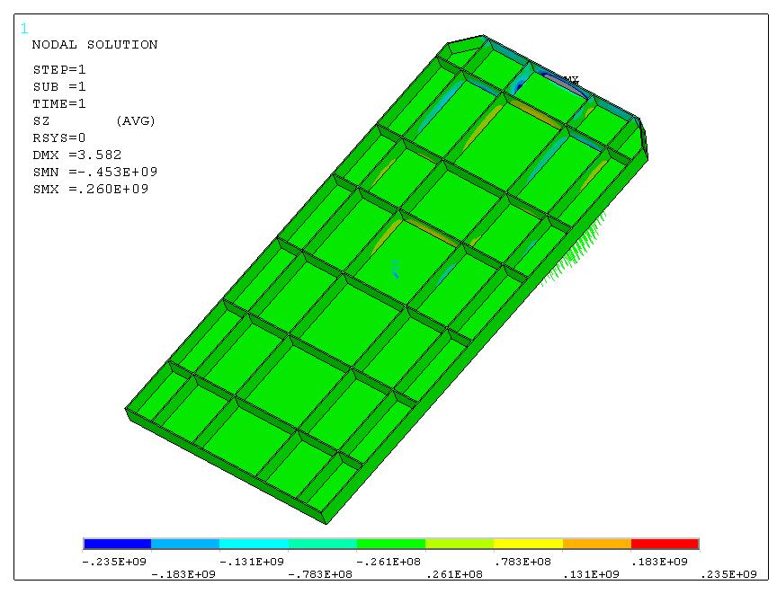
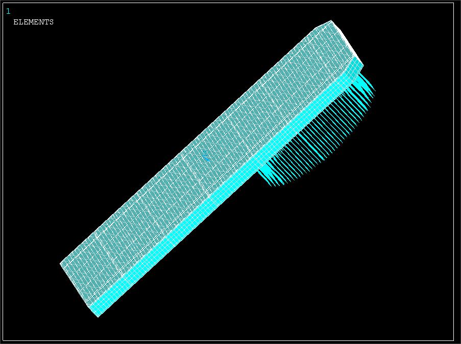
Gone are the days of simplistic load calculations and guesswork. Modern frontal panel design requires Finite Element Analysis (FEA) to accurately predict fatigue performance.
FEA simulates stress distribution across the entire panel geometry, identifying:
- Hot spots where stress concentrates (weld toes, geometry transitions)
- Von Mises stress levels compared to yield strength
- Predicted fatigue life under cyclic loading
- Crack propagation paths if failure occurs
Leading manufacturers use ANSYS finite element analysis to design marine fender systems, simulating stress distribution and deformation under various operating conditions to ensure the fenders remain stable, durable, and perform at their best.
FEA analysis should include:
1. Static load simulation (maximum berthing impact)
2. Cyclic load simulation (thousands of berthing cycles)
3. Weld fatigue assessment (per AWS D1.1 or equivalent)
4. Corrosion allowance modeling (thickness reduction over time)
| Parameter | Target Value | Consequence of Non-Compliance |
|---|---|---|
| Maximum Von Mises stress | < 0.6 × Yield Strength | Rapid low-cycle fatigue |
| Stress concentration factor at welds | < 2.0 | Crack initiation at weld toes |
| Predicted fatigue life | > 20 years at design cycles | Premature failure |
| Deflection under maximum load | < L/250 | Permanent deformation |
The choice of steel grade directly impacts both static strength and fatigue resistance.
| Steel Grade | Application | Fatigue Characteristics |
|---|---|---|
| Q235B / A36 / SS400 | Small to medium ports, vessels <5,000 tons | Adequate; standard endurance limit |
| Q355B / S355JR / A572 Gr50 | Large commercial ports, container terminals | Superior fatigue resistance – higher yield strength provides greater margin below endurance limit |
| Corten A/B | High-corrosion environments, offshore terminals | Forms protective patina; maintains fatigue properties |
| 316L Stainless Steel | Ultra-corrosive environments, chemical/LNG terminals | Excellent fatigue resistance; no corrosion-related fatigue acceleration |
Fatigue performance is not directly determined by yield strength alone—but higher yield strength allows designers to operate at a lower percentage of yield for the same absolute stress.
Example:
- A36 steel: Yield = 250 MPa. Operating at 150 MPa = 60% of yield (fatigue concern zone)
- S355JR steel: Yield = 355 MPa. Operating at 150 MPa = 42% of yield (below endurance limit threshold)
This stress margin is the difference between 10-year and 30-year panel life.
| Property | Carbon Steel (A36/Q235B) | HSLA Steel (S355JR/Q355B) |
|---|---|---|
| Yield Strength (ReL) | ≥235 MPa | ≥355 MPa |
| Tensile Strength (Rm) | 375–500 MPa | 490–650 MPa |
| Elongation (A) | ≥21% | ≥21% |
| Impact Toughness at -20°C | ≥34J | ≥34J |
Higher toughness materials resist crack propagation—a critical factor once fatigue cracks initiate.
Welded joints are almost always the location where fatigue cracks initiate. The welding process creates:
- Microstructural changes in the heat-affected zone (HAZ)
- Residual tensile stresses
- Minor geometric discontinuities (undercut, lack of fusion)
- Potential for hydrogen-induced cracking
| Principle | Implementation |
|---|---|
| Minimize stress concentration | Smooth transitions; grind weld toes |
| Avoid attachments to tension faces | Place brackets on compression side |
| Use full penetration welds | No partial penetration in primary load paths |
| Post-weld stress relief | Heat treatment or peening for critical welds |
| Inspect thoroughly | 100% NDT (magnetic particle or dye penetrant) on all structural welds |
| Requirement | Specification |
|---|---|
| Weld process | SAW or FCAW (preferred) |
| Preheat (for >25mm plate) | Per WPS (typically 50-100°C) |
| Interpass temperature | ≤250°C |
| NDT method | Magnetic Particle Inspection (MPI) or Dye Penetrant Testing (DPT) |
| Acceptance criteria | AWS D1.1 Class B or equivalent |
Corrosion is fatigue's worst enemy. A corroded steel section has effectively reduced thickness, which means higher stress for the same load—pushing the panel closer to its endurance limit.
| Corrosion Effect | Fatigue Consequence |
|---|---|
| Section thickness reduction | Higher operating stress → shorter fatigue life |
| Pitting | Creates stress concentration sites → crack initiation points |
| Hydrogen embrittlement | Reduced fracture toughness → faster crack propagation |
| Coating failure | Exposes bare steel to accelerated corrosion |
| System | Process | Service Life | Fatigue Impact |
|---|---|---|---|
| Hot-Dip Galvanizing | Sa 2.5 blast + ≥85μm zinc coating | 15–20 years | Maintains section thickness |
| Three-Layer Organic Coating | Epoxy zinc-rich primer + epoxy intermediate + polyurethane topcoat | 10–15 years | Requires regular inspection |
| Sacrificial Anodes | Attached to panel bottom | Supplemental | Prevents local pitting |
| Stainless Steel (316L) | No coating required | 30+ years | Eliminates corrosion fatigue concern |
> *"SME employs a multi-layer corrosion prevention system… featuring a triple-coat structure of primer, intermediate coat, and topcoat, or alternatively, an overall galvanized surface combined with a topcoat."*
For cold water climates, a corrosion allowance of 3mm per exposed face might be suitable. Much more is required where temperatures are higher and corrosion is greater.
Example calculation:
- Plate thickness required for structural strength: 12mm
- Corrosion allowance (both faces exposed): 3mm × 2 = 6mm
- Specified minimum thickness: 18mm
Without this allowance, the panel becomes structurally inadequate after 5–10 years of service.
Even the best-designed panel requires ongoing attention to achieve its full fatigue life.
| Frequency | Inspection Focus | Method |
|---|---|---|
| Daily Visual | Cracks near welds, loose fasteners, coating damage | Visual (unaided) |
| Quarterly | Weld condition, UHMW-PE pad wear, bolt torque | Visual + torque wrench |
| Annual | Coating thickness, corrosion pitting, stress cracks | DFT gauge + MPI |
| 5-Year Major | Full NDT of all structural welds | MPI or UT |
1. Weld toes – The most common fatigue crack initiation site
2. Bolt holes – Stress concentration points
3. Geometry transitions – Where panel thickness changes
4. Corrosion pitting – Potential crack nucleation sites
> *"A port in Singapore avoided a $50k fender replacement by replacing loose lashing rods during a routine inspection—catching the issue before it shifted the steel panel."*
We asked our global OEM clients about their experience with steel frontal panel fatigue. Here is what they shared:
> *"We used to specify the minimum thickness recommended by suppliers—usually 10mm for the face plate. After ten years, we had pitting corrosion through the entire section. Now we specify 16mm minimum with a 3mm corrosion allowance. The upfront cost increase was 15%, but we expect 25-year life instead of 10-year life."*
> — *Port Engineer, Northern Europe*
> *"FEA revealed that our original panel design had stress concentrations at the weld attachments that we never would have caught with hand calculations. We modified the geometry slightly, and the predicted fatigue life went from 8 years to 25+ years. That is the power of proper engineering."*
> — *Engineering Consultant, Southeast Asia*
> *"We learned the hard way that welding quality matters. One batch of panels had poor penetration on the critical welds. After two years, we saw cracks forming. Now we require 100% MPI on all structural welds before coating."*
> — *Maintenance Director, Middle East Terminal*
At Nanjing Taidun Marine Equipment Engineering Co., Ltd. , we manufacture not only rubber fenders and mooring bollards but also high-durability steel frontal panels designed for maximum fatigue resistance.
Our fatigue-resistant design process includes:
| Stage | Actions |
|---|---|
| FEA analysis | Full ANSYS simulation of static and cyclic loads |
| Material selection | S355JR or Q355B minimum for commercial terminals |
| Thickness design | PIANC-compliant with corrosion allowance |
| Weld specification | AWS D1.1 Class B with full NDT |
| Corrosion protection | Hot-dip galvanizing or three-layer epoxy system |
| Quality verification | Third-party inspection available (BV, ABS, LR, CCS) |
We serve brand owners, wholesalers, and production facilities in over 80 countries. When you partner with Taidun, you get documented fatigue analysis, certified materials, and panels designed for decades of reliable service—not just years.
Steel frontal panel fatigue resistance is not an optional engineering nicety—it is a critical safety and economic requirement for any port expecting long-term, reliable fender system performance.
Key takeaways:
- Fatigue causes 60%+ of fender system failures
- PIANC requires minimum 12mm for exposed plates
- Higher yield strength steels (S355JR/Q355B) provide superior fatigue margins
- FEA analysis is essential for identifying stress concentrations
- Corrosion protection directly impacts fatigue life
- Regular inspection catches cracks before they propagate
[Contact the Nanjing Taidun Engineering Team] for a frontal panel fatigue analysis consultation. Send us your berthing data and fender specifications, and we will provide FEA-validated panel designs with documented fatigue life predictions.
Q1: What is the minimum thickness required for a steel frontal panel?
A: Per PIANC guidelines, plates exposed on both faces require ≥12mm minimum. Plates exposed on one face require 9–10mm. However, corrosion allowances (typically 3mm per exposed face) must be added to achieve 15–20 year service life.
Q2: How does corrosion affect fatigue resistance?
A: Corrosion reduces section thickness (increasing stress) and creates pits that act as stress concentration sites. A panel that starts at 12mm thickness may have only 6–8mm remaining after 10 years without proper protection—drastically reducing fatigue life.
Q3: What is the best steel grade for fatigue resistance in marine environments?
A: For large commercial ports and container terminals, S355JR or Q355B (yield strength ≥355 MPa) provides superior fatigue margins. For harsh corrosive environments, Corten A/B or 316L stainless steel offers excellent long-term protection.
Q4: How often should I inspect frontal panels for fatigue cracks?
A: Daily visual checks for visible cracks; quarterly detailed inspections of weld areas; annual NDT (magnetic particle or dye penetrant) for critical welds; major 5-year full structural inspection.
Q5: Can FEA really predict fatigue life accurately?
A: Yes, when properly calibrated. FEA (using software like ANSYS) identifies stress concentration factors and hot spots, allowing engineers to predict fatigue initiation life with reasonable accuracy. However, weld quality and actual operating loads must match assumptions for predictions to hold.
1. Nanjing Taidun Marine Equipment Engineering Co., Ltd. (2026). *Which Steel Frontal Panel for Rubber Fender Fits Marine Berthing Needs?* [https://www.taidunmarine.com/which-steel-frontal-panel-for-rubber-fender-fits-marine-berthing-needs.html]
2. Nanjing Taidun Marine Equipment Engineering Co., Ltd. (2026). *Maintenance for Marine Fender Frontal Steel Panels*. [https://www.taidunmarine.com/maintenance-for-marine-fender-frontal-steel-panels.html]
3. Nanjing Taidun Marine Equipment Engineering Co., Ltd. (2026). *A36 Steel Frontal Panel for Rubber Fender: Load Distribution Design*. [https://www.taidunmarine.com/a36-steel-frontal-panel-for-rubber-fender-load-distribution-design.html]
4. Nanjing Taidun Marine Equipment Engineering Co., Ltd. (2026). *Complete Specification and Design Guide for Fender Steel Panels*. [https://www.taidunmarine.com/complete-specification-and-design-guide-for-fender-steel-panels-ensuring-durability-safety-and-performance-in-marine-berthing-systems.html]


